286 Rockwell Automation Publication 750-TG100B-EN-P - June 2019
Chapter 10 Wire Entry/Exit Bay Components
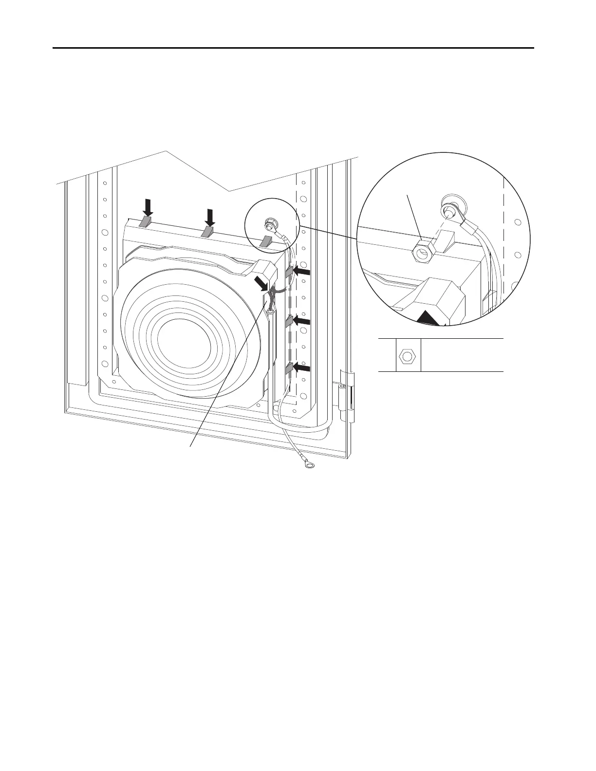
4. On the inside of the enclosure door, remove the M8 hex nut and washer
that secures the two ground wire lugs to the door, and remove the wires.
5. Disconnect the fan power wires from connector P1 on the fan assembly.
6. Press the tabs on the vent cover inward and pull the vent off the front of
the enclosure door.
Install the IP54/IP21, 400/800 mm Wide Door Vent Fan and Filter
Assembly
Install the IP54/IP21, 400/800 mm wide door vent fan, and filter assembly in the
reverse order of removal.
4
5
4
M8
13 mm
10.2 N•m (90 lb•in)
 Loading...


