EasyManuals Logo

Rockwell Automation PowerFlex 755TL User Manual

Rockwell Automation PowerFlex 755TL
352 pages
To Next Page IconTo Next Page
To Previous Page IconTo Previous Page
Page #86 background imageLoading...
Page #86 background image
86 Rockwell Automation Publication 750-TG100B-EN-P - June 2019
Chapter 5 Frame 6 Components
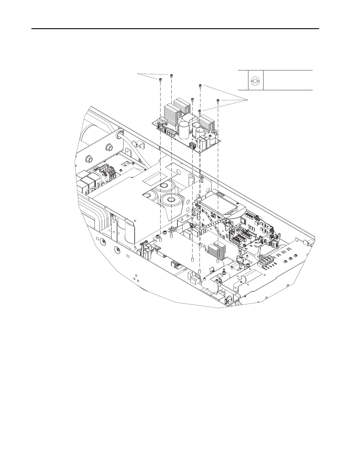
5. Remove the six M4 x 10 mm slotted-torx screws that secure the fan power
supply circuit board to the mounting plate and remove the circuit board.
Install the Fan Power Supply Circuit Board
Install the fan power supply circuit board in the reverse order of removal.
5
5
5
M4 x 10 mm
T20 or F - 6.4 mm (0.25 in.)
2.3 N
•m (20 lb•in)

Table of Contents

Questions and Answers:

Question and Answer IconNeed help?

Do you have a question about the Rockwell Automation PowerFlex 755TL and is the answer not in the manual?

Rockwell Automation PowerFlex 755TL Specifications

General IconGeneral
BrandRockwell Automation
ModelPowerFlex 755TL
CategoryDC Drives
LanguageEnglish

Related product manuals