76 Rockwell Automation Publication 750-TG100B-EN-P - June 2019
Chapter 5 Frame 6 Components
Remove the Cover
To remove the cover, follow these procedures.
Remove the Cover from the Chassis
Remove the cover from the chassis to access components within the drive or bus
supply.
1. Review the Product Advisories on page 14
.
2. Remove power from the system. See Remove Power from the System on
page 15
.
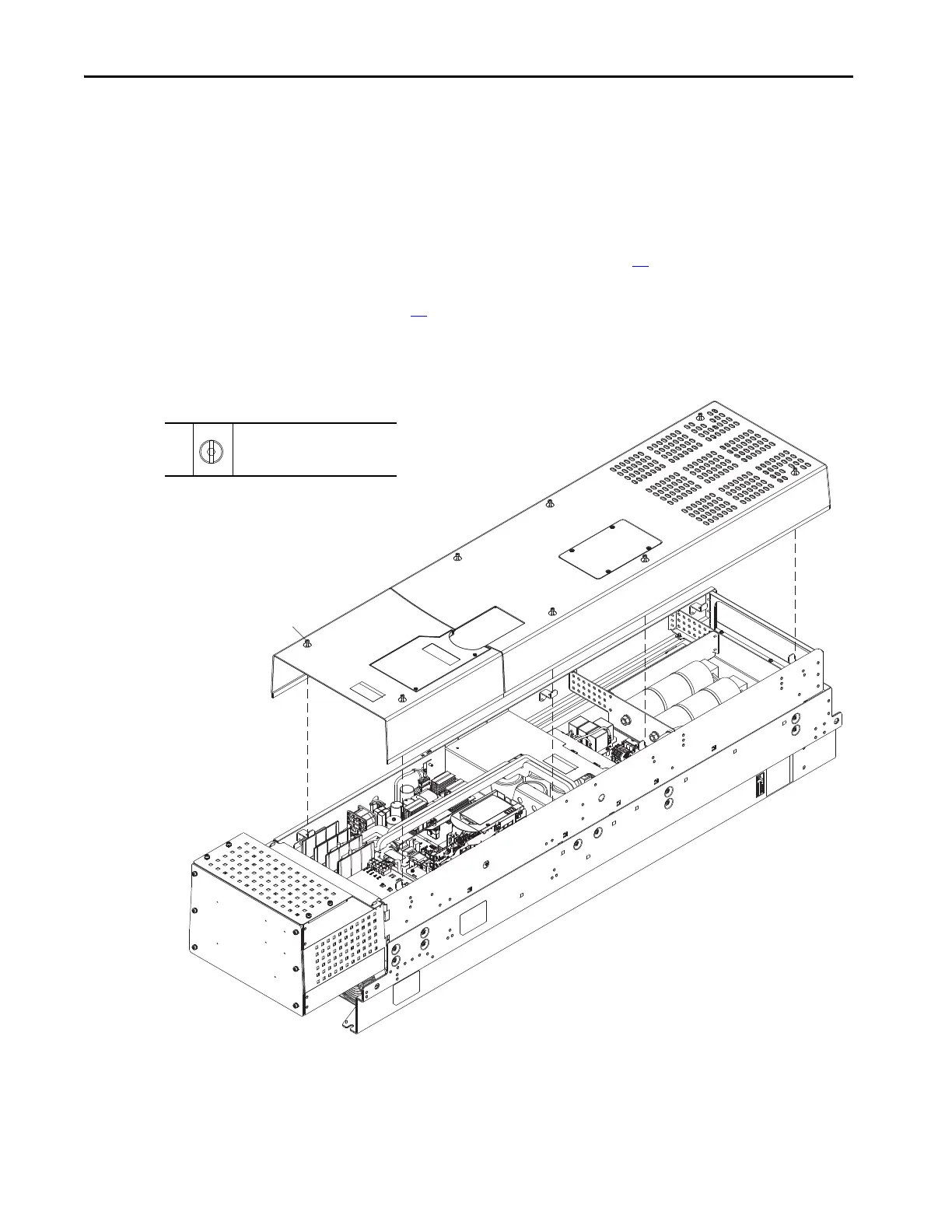
3. Loosen the eight M4 x 8 mm captive screws that secure the cover to the
assembly, and remove the cover.
Install the Cover
Install the cover in the reverse order of removal.
Shown with Optional Conduit Box Installed.
3
M4 x 8 mm
F - 6.4 mm (0.25 in.) or 4 mm hex
2.6 N•m (23 lb•in)
 Loading...


