Rockwell Automation Publication 750-TG100B-EN-P - June 2019 251
Power Bay Components Chapter 9
Remove the Power Interface Circuit Board
Follow these steps to remove and replace the power interface circuit board.
1. Review the Product Advisories on page 14
.
2. Remove power from the system. See Remove Power from the System on
page 15
.
3. Open the corresponding power bay enclosure door.
4. Remove the power module from the enclosure. See Power Module
Replacement on page 236
.
5. Remove the circuit board tray from the power module. See Circuit Board
Tray Rem o val o n page 244
.
6. Remove the power layer interface circuit board. See Power Layer Interface
Circuit Board Replacement on page 249
.
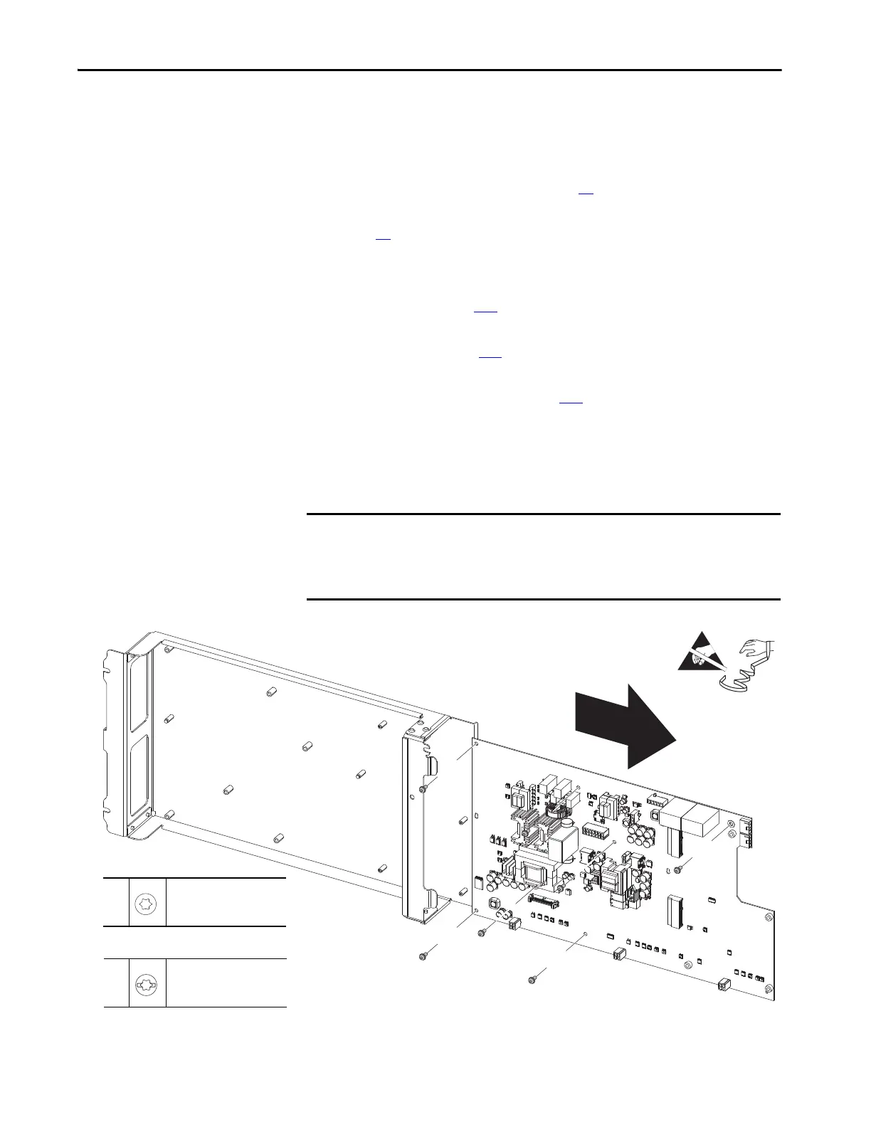
7. Remove the seven M4 x 10 mm or M4 x 18 mm torx screws that secure the
power interface circuit board to the circuit board tray and remove the
circuit board by lifting the board up and off the supports on the tray.
Retain the screws for reuse.
IMPORTANT The power interface circuit board replacement kit excludes screws. Therefore,
all existing screws for this board must be reused. Verify the screw size that is
supplied with your circuit board tray and apply the recommended torque
during reinstallation.
7
M4 x 10 mm
T20
2.6 N•m (23.0 lb•in)
7
M4 x 18 mm
T20
2.6 N•m (23.0 lb•in)
OR
 Loading...


