110 Rockwell Automation Publication 750-TG100B-EN-P - June 2019
Chapter 6 Frame 7 Components
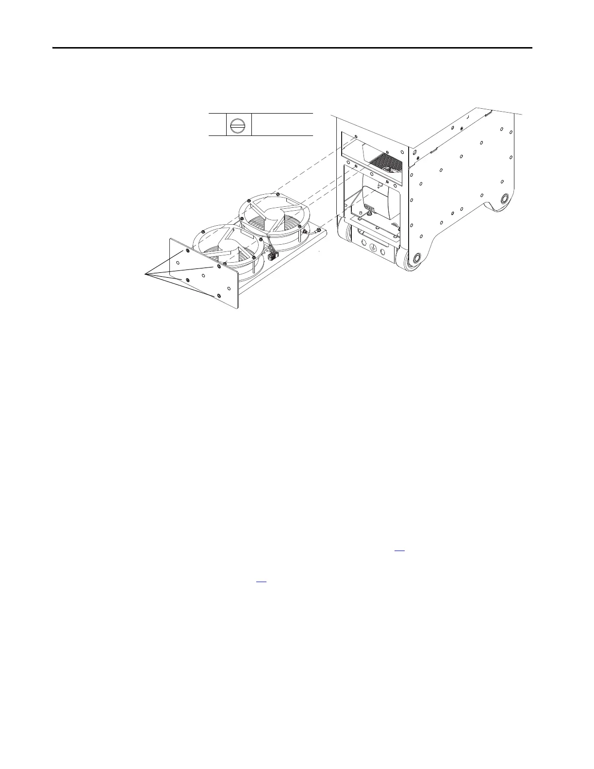
5. Loosen the four captive M5 screws on the front of the fan assembly and
slide the assembly out of the chassis.
Install the Power/Filter Module Fan Assembly
Install the power/filter module heatsink fan assembly in the reverse order of
removal.
Remove the Protective
Guard
You must remove the protective guard to access certain components in the
enclosure.
Remove the Protective Guard
Follow these steps to remove the protective guard.
1. Review the Product Advisories on page 14
.
2. Remove power from the system. See Remove Power from the System on
page 15
.
3. Open the enclosure door.
 Loading...


