EasyManuals Logo

Rockwell Automation PowerFlex 755TL User Manual

Rockwell Automation PowerFlex 755TL
352 pages
To Next Page IconTo Next Page
To Previous Page IconTo Previous Page
Page #121 background imageLoading...
Page #121 background image
Rockwell Automation Publication 750-TG100B-EN-P - June 2019 121
Frame 7 Components Chapter 6
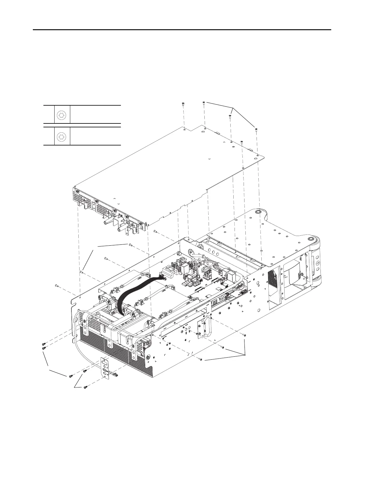
6. Remove the two M5 x 12 mm torx screws that secure the I/O connections
plate to the top of the power module chassis and remove the panel.
7. Remove the three M5 x 12 mm torx screws that secure the bus bar support
to the right, top side of the power module chassis.
8. Remove the 13 M5 x 10 mm torx screws that secure the right side cover to
the power module and remove the cover.
6, 7
M5 x 12 mm
T25
2.6 N•m (23.0 lb•in)
7
6
8
8
8
8
M5 x 10 mm
T25
6.0 N•m (53.0 lb•in)

Table of Contents

Questions and Answers:

Question and Answer IconNeed help?

Do you have a question about the Rockwell Automation PowerFlex 755TL and is the answer not in the manual?

Rockwell Automation PowerFlex 755TL Specifications

General IconGeneral
BrandRockwell Automation
ModelPowerFlex 755TL
CategoryDC Drives
LanguageEnglish

Related product manuals