158 Rockwell Automation Publication 750-TG100B-EN-P - June 2019
Chapter 7 Control Bay and Control Pod Components
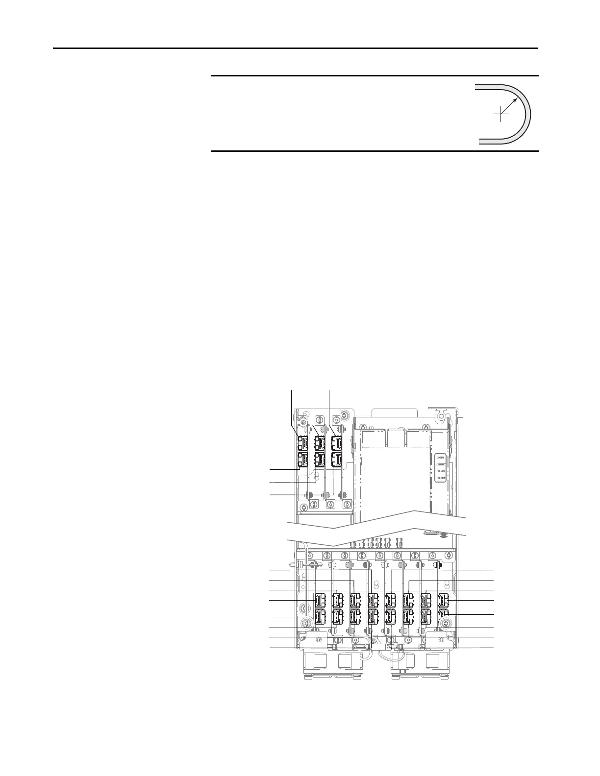
8. Remove the fiber-optic cables from the cable management devices in the
control pod.
9. Disconnect the AC precharge circuit board and torque accuracy module
fiber-optic cables from the ACP0 and ACPC1/TAM port on the fiber
transceiver board, respectively. Carefully coil the fiber-optic cable and
secure in a protected location. Follow the minimum bend radius
requirement.
10. For each line side inverter, disconnect the fiber-optic cable from the Ln
port on the fiber transceiver board. Carefully coil the fiber-optic cable and
secure in a protected location. Follow the minimum bend radius
requirement.
11. For each motor side converter, disconnect the fiber-optic cable from the
Mn port on the fiber transceiver board. Carefully coil the fiber-optic cable
and secure in a protected location. Follow the minimum bend radius
requirement.
IMPORTANT
Minimum inside bend radius for fiber-optic cable is 50 mm
(2 in.). Any bends with a shorter inside radius can
permanently damage the fiber-optic cable. Signal
attenuation increases as inside bend radius is decreased.
ACP0 L0 L1
ACP1 / TAM
M0
M1
L8
L6
L4
L2
L9
L7
L5
L3
M2
M4
M6
M8
M3
M5
M7
M9
 Loading...


