18 Rockwell Automation Publication 750-TG100B-EN-P - June 2019
Chapter 1 Before You Begin Tests, Maintenance, or Repairs
4. For common bus inverters with DC precharge, complete steps a…e:
a. Turn the DC precharge disconnect switch to the “Off ” position.
a. Wait 15 minutes.
b. Open the enclosure door.
c. Close and lock the hasp on the molded case switch.
d. Lock the fused disconnect switch.
e. If a control bay is used, turn the selector switch to the “Off ” position
and lock the switch.
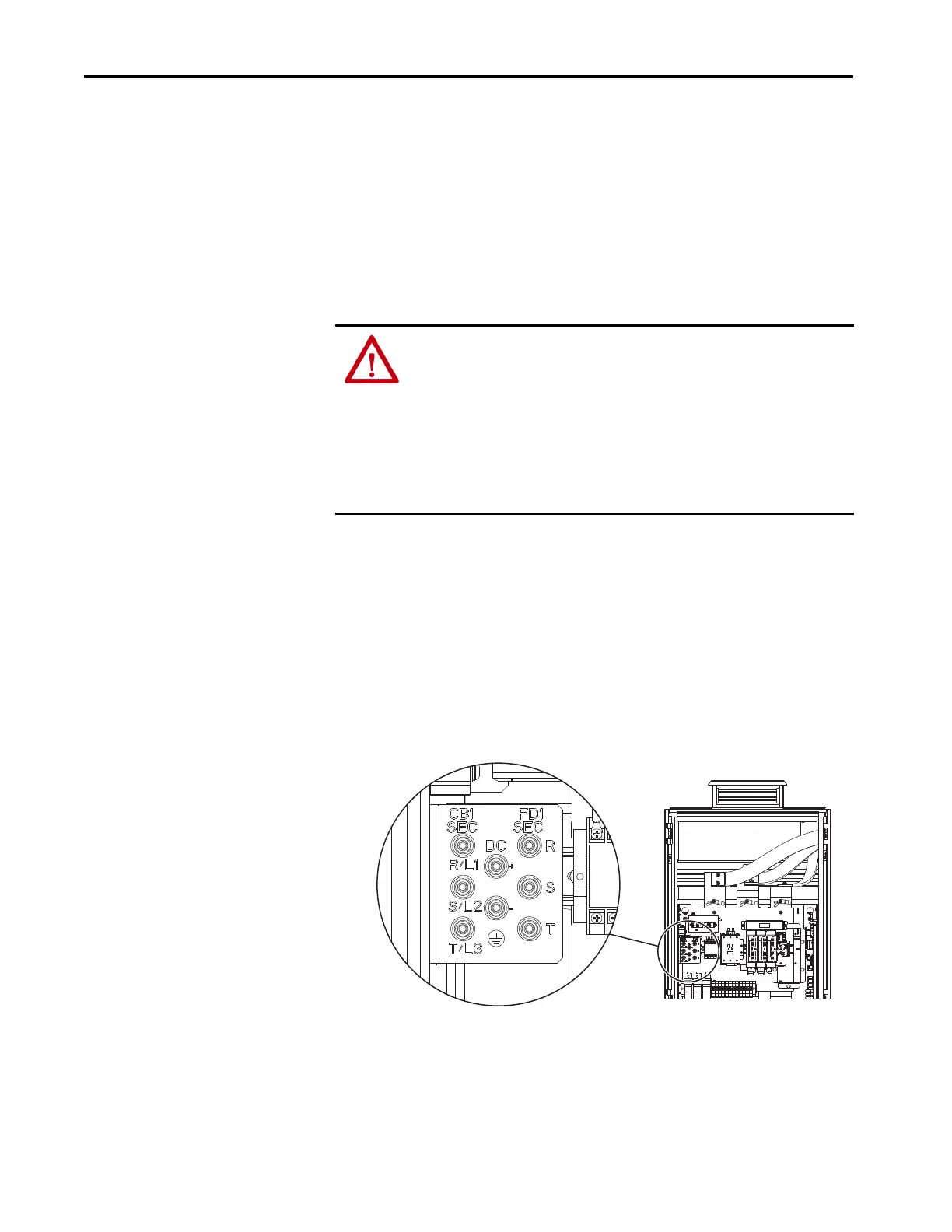
5. For regenerative drives and bus supplies, measure the AC input and DC
bus voltage at the following testpoint sockets in the input bay to verify that
there is no voltage present:
• Using the circuit breaker output (CB1 SEC) testpoints R/L1, S/L2,
and T/L3, measure L to L and L to chassis GND.
• By using the fused disconnect output (FD1 SEC) testpoints R, S, and
T, measure L to L and L to chassis GND.
• By using the DC bus testpoints +DC and –DC, measure +DC to
–DC, +DC to chassis GND, and –DC to chassis GND.
ATTENTION: To avoid an electric shock hazard, verify that there is no AC input
and DC bus voltage before servicing by taking these measurements:
• Verify that there is no AC input voltage present using the R/L1, S/L2, and T/L3
test point sockets in the input bay by measuring L to L and L to GND.
• Verify that there is no AC input voltage present using the R, S, and T testpoint
sockets in the input bay by measuring L to L and L to GND.
• Verify that there is no DC bus voltage present using the +DC to –DC testpoints
in the input bay by measuring +DC to –DC, +DC to GND, and –DC to GND.
Frame 9, IP21 UL Type 1 Input Bay Shown
 Loading...


