218 Rockwell Automation Publication 750-TG100B-EN-P - June 2019
Chapter 9 Power Bay Components
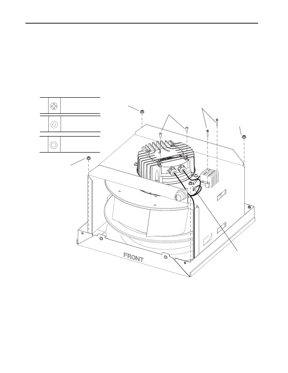
11. Remove the two M3 x 20 mm Phillips head screws (white) that secure the
interconnection terminal block to the fan housing and remove the
terminal block.
12. Remove the two M4 x 11 mm torx screws that secure the fan power
connector to the fan and remove the connector and wires.
13. Remove the four M5 x 5 mm nuts that secure the fan assembly and housing
to fan base and carefully lift the fan assembly and housing from off the
base. As you lift the fan assembly and housing, pull the wire harness
carefully through the opening in the enclosure roof.
13
M5 x 5 mm
8 mm
6.5 N
•m (58 lb•in)
12
M4 x 11 mm
T20
3 N•m (26.5 lb•in)
11
M3 x 20 mm
P1
0.6 N•m (5.3 lb•in)
8
9
10
10
10
10
 Loading...


