Rockwell Automation Publication 750-TG100B-EN-P - June 2019 227
Power Bay Components Chapter 9
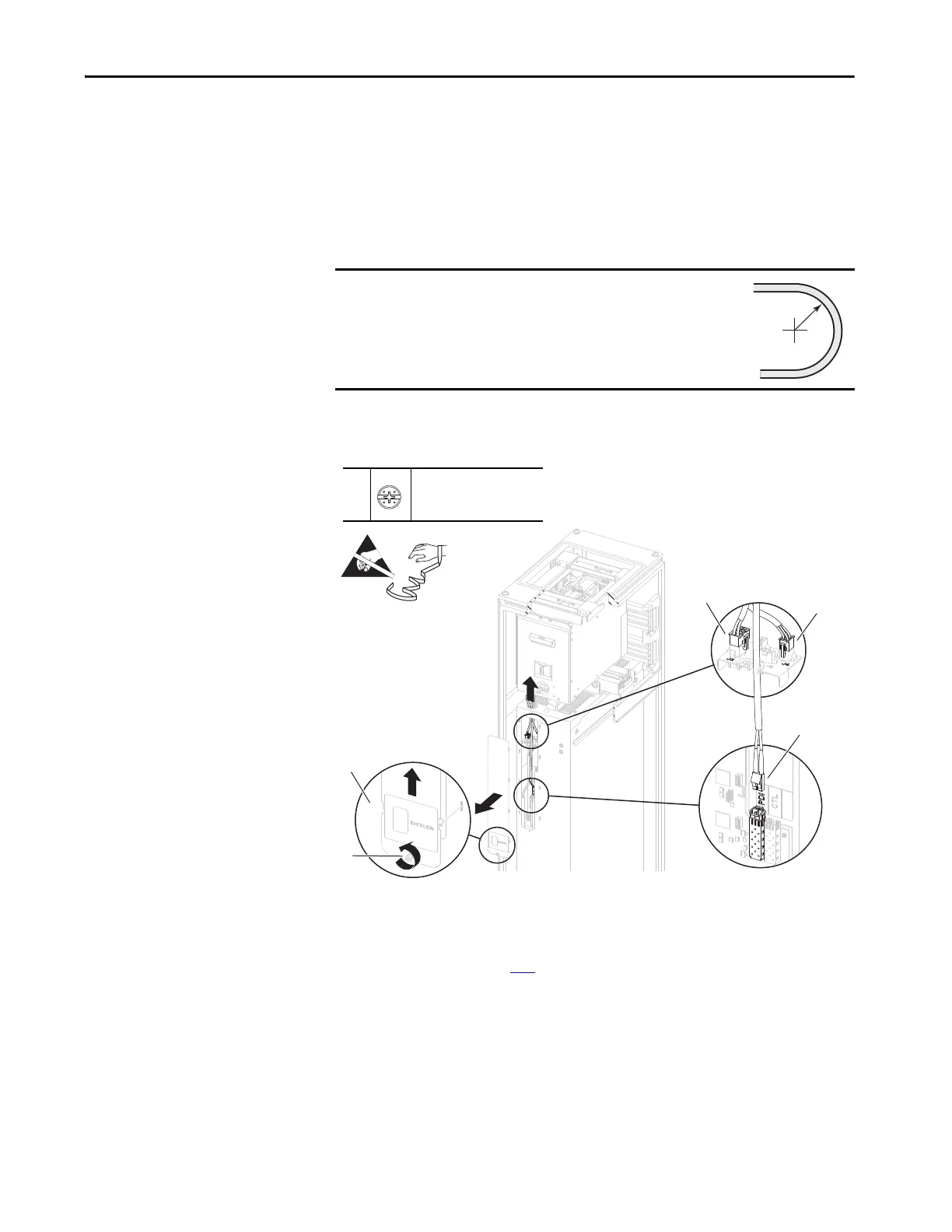
8. Loosen the thumb screw that secures the connections cover to the front of
the power module.
9. Use the screw to lift the connections cover up and off the power module
chassis.
10. Disconnect connector P3 from J3 on the power module I/O control panel.
11. Disconnect connector P4 from J4 on the power module I/O control panel.
12. Without bending the cable to a radius less than 50 mm (2 in.), remove the
fiber-optic cable from the transceiver in the PDI port on the power layer
interface circuit board.
13. Remove the fiber-optic cable from the power module chassis.
14. Remove the power module from the enclosure. See Power Module
Replacement n page 236
.
IMPORTANT
Minimum inside bend radius for fiber-optic cable is 50 mm
(2 in.). Any bends with a shorter inside radius can
permanently damage the fiber-optic cable. Signal
attenuation increases as inside bend radius is decreased.
9
11
8
8
–
P2 or F - 6.4 mm (0.25 in.)
1.8 N•m (16 lb•in)
 Loading...


