240 Rockwell Automation Publication 750-TG100B-EN-P - June 2019
Chapter 9 Power Bay Components
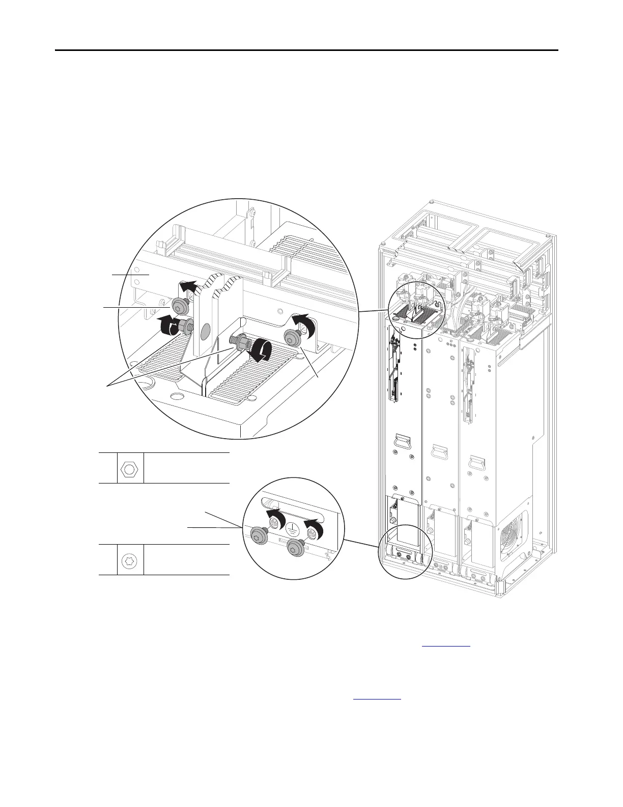
13. Loosen the two M10 x 10 mm hex nuts and bolts that secure the power
input/output terminals to the DC precharge module or DC link fuse
terminals.
14. Remove the two M10 x 20 mm torx screws that secure the power module
chassis to the control bus frame.
15. Leave the two M10 x 20 mm screws that secure the power module chassis
to the floor mounting bracket while preparing the PowerFlex 750-Series
service cart or service ramp.
16. To remove the module by using the service cart, follow the detailed
instructions in the PowerFlex 750-Series Service Cart and DCPC Module
Lift Installation Instructions, publication 750-IN105
.
To remove the module using PowerFlex 755TM service ramp, follow the
procedures that are detailed in the PowerFlex 755T Module Service Ramp
Instructions, publication 750-IN108
.
15: Leave these M10 screws in place while
preparing the service cart or ramp.
Control bus frame
13
14
14
17: Remove these M10 screws.
13
M10 x 10 mm
17 mm
38 N•m (336 lb•in)
14,
17
M10 x 20 mm
T45
42.4 N•m (375 lb•in)
 Loading...


