Rockwell Automation Publication 750-TG100B-EN-P - June 2019 261
Power Bay Components Chapter 9
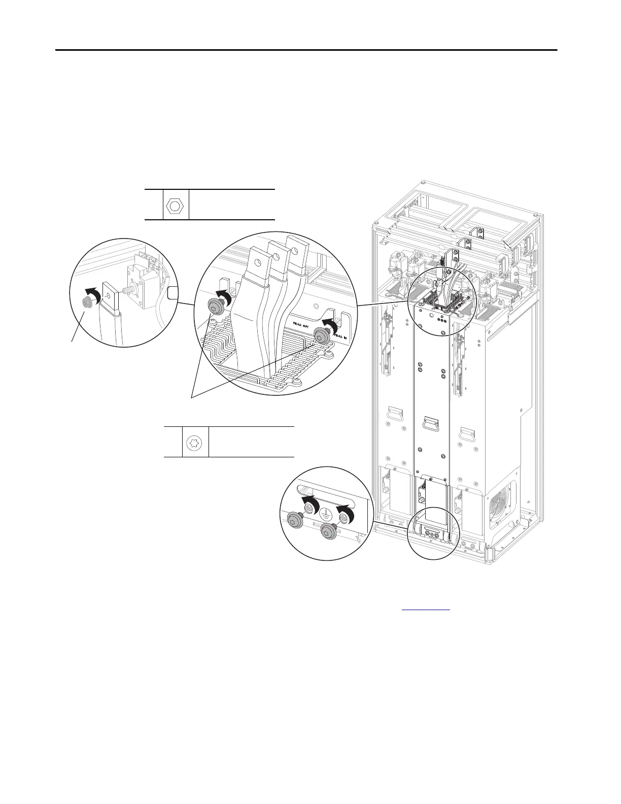
11. Remove the three M12 x 13 mm hex nuts that secure the flexible bus cables
to the AC input fuse terminals and remove the flexible bus cables.
12. Remove the two M10 x 20 mm torx screws that secure the LCL filter
module chassis to the control bus frame.
13. Leave the two M10 x 20 mm screws that secure the LCL filter module
chassis to the floor mounting bracket while preparing the PowerFlex 750-
Series service cart.
14. Secure the service cart to the floor mounting bracket in the enclosure. See
the PowerFlex 750-Series Service Cart and DCPC Module Lift
Installation Instructions, publication 750-IN105
, for information on by
using the service cart.
15. To release the LCL filter module, remove the two remaining M10 screws.
16. Remove the LCL1 filter module from the enclosure.
13: Leave these M10 screws in place while
preparing the service cart or ramp.
15: Remove these M10 screws.
11
M12 x 13 mm
19 mm
45 N•m (398 lb•in)
12,
15
M10 x 20 mm
T40
42.4 N•m (375 lb•in)
11
12
15
 Loading...


