EasyManuals Logo

Rockwell Automation PowerFlex 755TL User Manual

Rockwell Automation PowerFlex 755TL
352 pages
To Next Page IconTo Next Page
To Previous Page IconTo Previous Page
Page #288 background imageLoading...
Page #288 background image
288 Rockwell Automation Publication 750-TG100B-EN-P - June 2019
Chapter 10 Wire Entry/Exit Bay Components
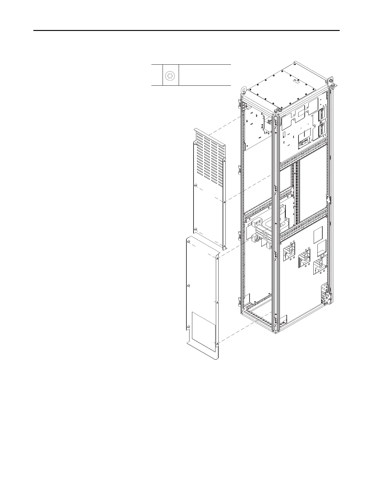
4. Loosen the 12 screws that secure the guards to the enclosure and remove
the guards.
5. Remove the two M6 x 25 mm torx screws that secure the thermal switch
assembly to the mounting bracket on the bus bar and remove the assembly.
Retain the screws, guard, and clamp for reuse.
4
M5.5 x 13 mm
T25
2.6 N
•m (23 lb•in)
400 mm Wide Entry/Exit Wire Bay Shown.

Table of Contents

Questions and Answers:

Question and Answer IconNeed help?

Do you have a question about the Rockwell Automation PowerFlex 755TL and is the answer not in the manual?

Rockwell Automation PowerFlex 755TL Specifications

General IconGeneral
BrandRockwell Automation
ModelPowerFlex 755TL
CategoryDC Drives
LanguageEnglish

Related product manuals