Rockwell Automation Publication 750-TG100B-EN-P - June 2019 295
Start Up After Repairs Chapter 11
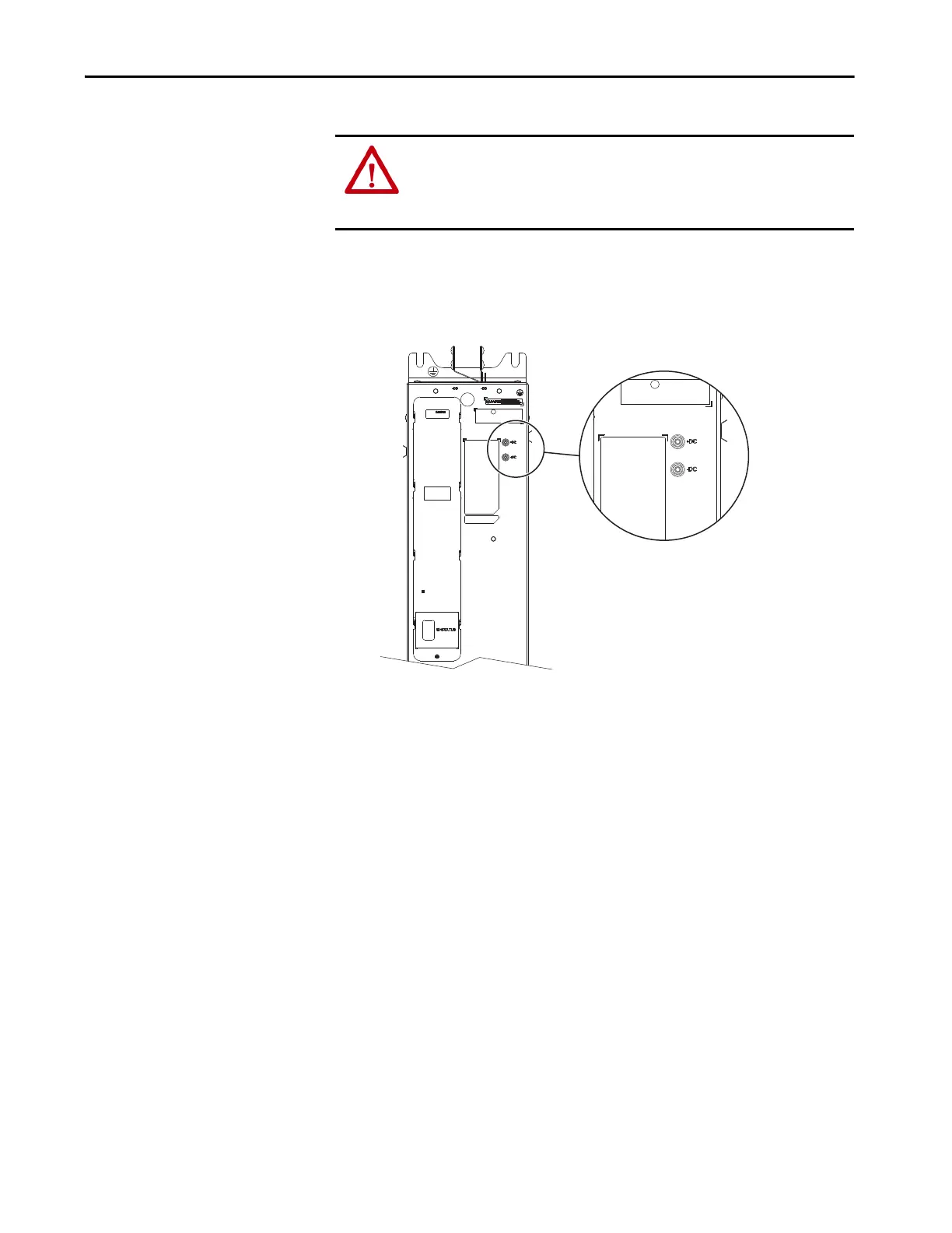
2. For common bus inverters, use the DC bus testpoints +DC and –DC on
the front of the power modules to measure the DC bus voltage of all power
modules and verify that there is no voltage present on the bus capacitors.
Measure +DC to –DC, +DC to chassis GND, and –DC to chassis GND.
ATTENTION: To avoid an electric shock hazard, verify that the voltage on the
bus capacitors has discharged completely before servicing. Verify that there is
no DC bus voltage present by using the +DC to –DC testpoints on all power
modules and by measuring +DC to –DC, +DC to GND, and –DC to GND.
 Loading...


