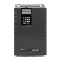
Do you have a question about the Rockwell Automation RELIANCE ELECTRIC SP500 and is the answer not in the manual?
| Category | DC Drives |
|---|---|
| Output Voltage | 0-500 VDC |
| Control Method | Digital |
| Manufacturer | Rockwell Automation |
| Enclosure Rating | NEMA 1 |
Identifies the intended audience for the manual, focusing on qualified electrical personnel.
Outlines the fundamental tasks required for installing the SP500 drive, including planning and checks.
Provides contact information for obtaining technical support and assistance from Reliance Electric.
Lists the key features and capabilities of the SP500 AC drive, such as keypad control and drive protection.
Explains the operational principles, components, and control methods of the SP500 drive.
Details how to interpret the drive's model number to understand its specifications and ratings.
Presents a table detailing the power ratings and NEMA enclosure types for various SP500 drive models.
Shows diagrams illustrating the physical location of major components within different drive enclosures.
Lists available optional kits for the SP500 drive, such as braking kits, with their model numbers.
Specifies environmental conditions, temperature, and humidity requirements for drive installation.
Provides drive dimensions for enclosures A through D to calculate installation space needs.
Details required minimum clearances around the drive for adequate ventilation and heat dissipation.
Covers essential considerations for drive wiring, including conduit size, wire specifications, and lead lengths.
Specifies the recommended wire gauge and size for AC input and output power connections.
Advises on maximum allowable lengths for motor leads to prevent electrical disturbances.
Provides guidance on selecting appropriate fuses for AC input line branch circuit protection.
Outlines requirements for providing an external, hardwired emergency stop circuit for safety.
Discusses factors for selecting and applying motors with the SP500 drive, including horsepower and current ratings.
Instructions on how to physically mount the drive unit to a surface using designated mounting holes.
Guidelines for properly routing signal, control, and power wiring in separate conduits to avoid interference.
Covers the installation of external components such as disconnects, transformers, and contactors.
Explains how to configure the analog input for voltage or current signals using jumper J6.
Outlines essential checks and preparations related to the motor before installation.
Step-by-step instructions for connecting the AC input power to the drive terminals.
Details on connecting various control and signal wires to the regulator board's terminal strip.
Instructions for connecting analog speed reference signals using terminals 1-3.
Information on connecting digital inputs for control signals using terminals 6-11.
Instructions for connecting the AC output power wiring from the drive to the motor terminals.
Essential procedures for properly grounding the drive, motor, and associated components for safety.
Procedures for verifying correct wiring and component installation before energizing the drive.
Steps to confirm proper drive functionality and motor operation after installation.
Explains the four-character LED display and its indications during operation and diagnostics.
Describes the function of each of the six membrane keys used for drive control and programming.
Explains the meaning of the drive status and monitor mode LEDs on the keypad interface.
Details how to enter and navigate the drive's parameter programming mode to adjust settings.
Describes how to view drive status, output data, and selected parameters in monitor mode.
Explains how to use the keypad for local control of the drive, including start, stop, and speed adjustments.
Outlines the procedure for accessing, viewing, and modifying drive parameter values.
Explains how to use parameter F-20 to enable password protection for drive programming.
Provides detailed explanations for all available drive parameters, covering their range, default settings, and function.
Safety procedure to check for residual voltage in DC bus capacitors before internal component access.
Guide to diagnosing and resolving drive faults by identifying fault codes and their causes.
Instructions on how to view, navigate, and clear the drive's internal error log containing fault history.
Steps to diagnose power module issues by checking circuitry with the drive de-energized.
Comprehensive technical data including service conditions, dimensions, and environmental specifications for the SP500 drive.
A table template provided for users to record custom parameter settings for future reference.
An alphabetically organized list of all programmable parameters with their corresponding parameter numbers.
Lists sections of the EN-60204-1 standard to which the SP500 drive complies.
Provides an overview of EMC standards and requirements relevant to the SP500 drive installation.
Details the conditions the SP500 drive must meet, including model number specification and CE marking.
Guidance on identifying and installing the AC Mains Filter to meet EMC emission standards.
Specific wiring guidelines for the drive, filter, motor leads, and control stations to ensure EMC compliance.
Instructions for connecting the AC Mains Filter output to the drive’s AC input terminals.
Requirements for motor lead wiring, including conduit type and length, for EMC compliance.
Guidelines for wiring operator control stations using rigid, conductive conduit or screened cable.
Wiring requirements for control I/O and signal wiring to maintain EMC compliance.
Lists available replacement parts for various SP500 drive models and horsepower ratings.
Definitions of technical terms and acronyms used throughout the SP500 AC Drive manual.
An alphabetical listing of topics and their corresponding page numbers for quick reference.


