10
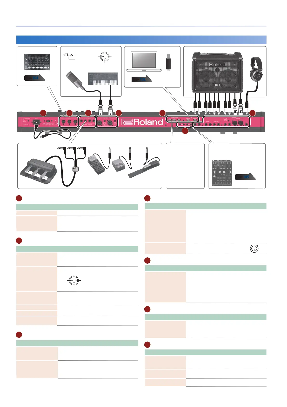
Panel Descriptions
A
Power Supply
Controller Explanation
[L] switch
This turns the power on/off.
AC IN jack
Connect the included power cord to this connector.
* To prevent malfunction and equipment failure, always turn
down the volume, and turn off all the units before making any
connections.
B
OUTPUT jack
Controller Explanation
PHONES jack
You can connect a set of headphones here.
Even if headphones are connected, an audio signal is
sent from the OUTPUT jacks and BALANCED OUT jacks.
MAIN OUT jacks (L, R)
(Balanced)
These are balanced output jacks for audio signals.
Connect them to your mixer.
1: GND
2: HOT
3: COLD
TIP: HOT
RING: COLD
SLEEVE: GND
MAIN OUT jacks (L/MONO, R)
These are output jacks for audio signals. Connect them
to your amp. If you’re outputting in mono, connect the
L/MONO jack.
SUB OUT 1 jacks (L, R)
These are output jacks for sub-out audio.
SUB OUT 2 jacks
(L, R)
ANALOG FILTER OUT
jacks (1, 2)
These output the sound that has passed through the
analog filter section.
C
CV/GATE jacks
Controller Explanation
GATE OUT jacks
(1, 2)
These jacks output note-on/off. They output +5 V.
Depending on the settings, GATE OUT 2 can also be
used as CV OUT.
CV OUT jacks
(1, 2)
These jacks output pitch. If you’ve specified a transpose
or octave shift setting, the voltage changes according
to the setting.
These jacks support OCT/V (Hz/V is not supported).
D
INPUT jack
Controller Explanation
MIC/LINE INPUT jacks
(1, 2) (Balanced)
Connect a mic, audio device, or external synthesizer
etc. to these jacks.
The MIC/LINE INPUT jacks support XLR-type and TRS-
type plugs. The XLR-type connections support 48 V
phantom power, allowing you to connect condenser
mics that use phantom power (phantom power supply:
DC 48 V, 10 mA Max). Stereo input via a TRS plug is not
supported.
LEVEL knobs
(1, 2)
Adjusts the input level of the MIC
INPUT jack.
MIN
MAX
E
FOOT PEDAL jack
Controller Explanation
PEDAL jacks
(CTRL 1, CTRL 2/L,
CTRL 3/C, HOLD/R)
If you connect a pedal switch (sold separately: DP
series) to the HOLD/R jack, you can use it as a damper
pedal. You can also assign various functions to the
pedals that are connected to the CTRL 1, CTRL 2/L, and
CTRL 3/C jacks.
* Use only the specified expression pedal. By connecting any
other expression pedals, you risk causing malfunction and/or
damage to the unit.
F
MIDI jack
Controller Explanation
MIDI connectors
(IN, OUT 1,
OUT 2/THRU)
Used for connecting external MIDI devices and for
transmission of MIDI messages.
The OUT 2/THRU connector’s function can be switched
to operate either as MIDI THRU or as MIDI OUT.
G
USB port
Controller Explanation
USB MEMORY port
Use a commercially available USB flash drive. However,
we cannot guarantee that all commercially available
USB flash drives will work.
USB COMPUTER port
Connect this to your computer to transfer performance
data and audio signals.
EXTERNAL DEVICE jacks
(1, 2, 3)
Connect these to an external USB device.
Pin assignment of MAIN
OUT jack
Rear Panel (Connecting Your Equipment)
* To prevent malfunction and equipment failure, always turn down the volume, and turn off all the units before making any connections.
A D E F G
Power cordto Power outlet
Pedal unit
(RPU-3)
Expression pedal (EV-5)
or Pedal switch (DP Series)
HeadphonesMonitor speakers (powered)
Microphone Synthesizer
page
104
Computer USB flash drive
page
102
Pin assignment of MIC/LINE INPUT jack
External USB device
MIDI device
1: GND2: HOT
3: COLD
1: GND 2: HOT
3: COLD
TIP: HOT
RING: COLD
SLEEVE: GND
Analog synthesizers or Eurorack
modules that are equipped with
CV/gate input jacks.
page
105
C
B
 Loading...