105
About the FANTOM’s CV/GATE
The FANTOM is equipped with two sets of CV/GATE output
jacks, and by connecting these to analog synthesizers that are
equipped with CV/GATE input jacks, you can control their note
on/off and pitch.
About CV/GATE signals
CV stands for “Control Voltage,” and is an electrical signal (control
voltage) used to control the behavior of an analog synth or Eurorack
module. GATE is a signal used to control the beginning and end of an
envelope.
Jack Explanation
GATE OUT 1 jack
GATE OUT 2 jack
These jacks output note on/off.
Outputs +5 V.
CV OUT 1 jack
CV OUT 2 jack
These jacks output pitch. If you’ve made transpose or
octave shift settings, this voltage changes accordingly.
These jacks support OCT/V (it does not support Hz/V).
Normally, the CV OUT 1 jack and the GATE OUT 1 jack are used as a pair.
Likewise, the CV OUT 2 jack and the GATE OUT 2 jack are used as a pair.
MEMO
By making a system setting, GATE OUT 2 can be changed to CV OUT (CV3). For
details, refer to “System Parameters” (p. 112).
Using CV/GATE
Here’s how to use CV/GATE to control an analog synthesizer. In
the same way as for “Controlling an External MIDI Device (EXT
MIDI OUT),” the analog synthesizer is controlled from an EXT
zone using CV/GATE.
Here we explain an example in which we connect the CV OUT 1
jack and GATE OUT 1 jack to an analog synthesizer, and control
it from zone 1.
1.
Connect the CV OUT 1 jack and the GATE OUT
1 jack to the analog synthesizer’s CV IN jack
and GATE IN jack respectively.
NOTE
Depending on the manufacturer or model, the CV jack and GATE jack
might be named differently. For details, refer to the owner’s manual of
your analog synthesizer.
2.
Press the [MENU] button.
3.
Touch <SYSTEM>.
The SYSTEM screen appears.
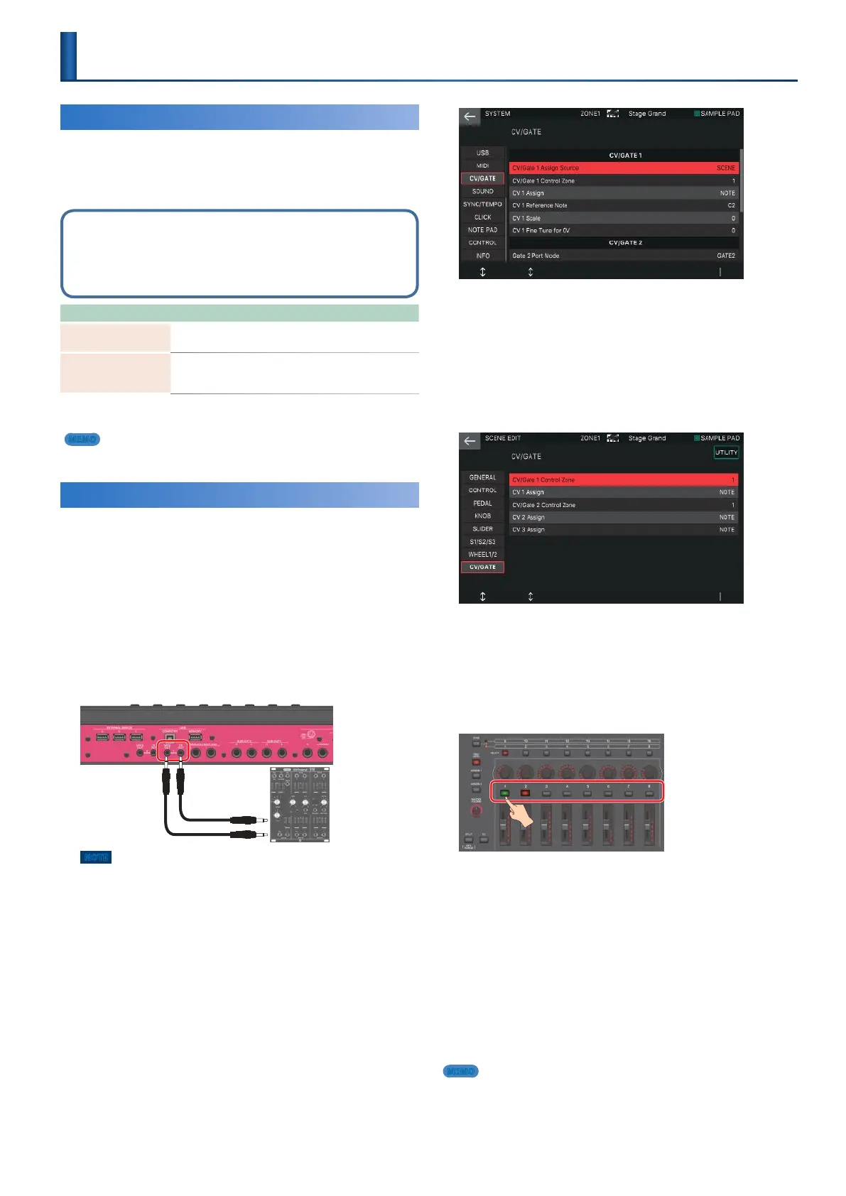
4.
Touch <CV/GATE> tab.
5.
Set the CV/Gate Assign Source value to
“SCENE.”
Now the control settings for CV/Gate 1 (CV OUT 1 jack and GATE OUT 1
jack) can be set individually for each scene.
Save the system parameters as necessary.
6.
Press the [MENU] button.
7.
Touch <SCENE EDIT>.
The SCENE EDIT screen appears.
8.
Touch <CV/GATE> tab.
9.
Set the CV/Gate 1 Control Zone to “1.”
Now you can use zone 1 to control CV/Gate 1 (CV OUT 1 jack
and GATE OUT 1 jack).
10.
11.
Zone 1 is now an EXT zone
If the button is not lit green, hold down the [SHIFT] button and
pressing corresponding ZONE INT/EXT button so that it is lit
green (EXT setting).
When this is lit green (EXT setting), CV/Gate signals are
output.
When the ZONE INT/EXT buttons of multiple zones are lit, the
situation is the same as for EXT MIDI OUT; the combination
of zones specified by the ZONE SELECT buttons (the current
zone) determines whether CV/Gate signals are output to the
external sound module.
12.
MEMO
If you want to keep the settings, save the scene. In this example, the scene
parameters are used to make CV/Gate 1 control settings, so you can use this
to control an analog synthesizer only in specific scenes.
Make zone 1 the current zone.
Press the ZONE INT/EXT button of zone 1 so
that it is lit green.
When you play the keyboard, CV/Gate signals are
output, controlling the analog synthesizer.
Controlling an Analog Synthesizer
(CV/GATE OUT)
 Loading...