Hazardous Area Oxymitter 5000
1-8
Instruction Manual
IM-106-350C, Rev 2.2
July 2008
A typical system installation with integral electronics is illustrated in
Figure 1-6. A typical system installation with remote electronics is illustrated in
Figure 1-7.
A source of instrument air is optional at the Hazardous Area Oxymitter 5000
for reference air use. Since the unit can be equipped with an in-place
calibration feature, provisions can be made to permanently connect
calibration gas bottles to the Hazardous Area Oxymitter 5000.
If the calibration gas bottles will be permanently connected, a check valve is
required next to the calibration fittings on the integral electronics.
This check valve is to prevent breathing of the calibration gas line and
subsequent flue gas condensation and corrosion.
The check valve is in addition to the stop valve in the calibration gas kit and
solenoid valves in the IMPS 4000 or SPS 4001B.
NOTE
The integral electronics is rated NEMA 4X (IP66) and is capable of operation
at temperatures up to 85°C (185°F).
The optional LOI is also rated for operation at temperatures up to 85°C
(185°F). The infrared keypad functionality will deg rade at temperatures above
70°C (158°F).
Retain the original packaging for the Hazardous Area Oxymitter 5000, in case
the components are to be shipped to another site. This packaging is designed
to protect the product.
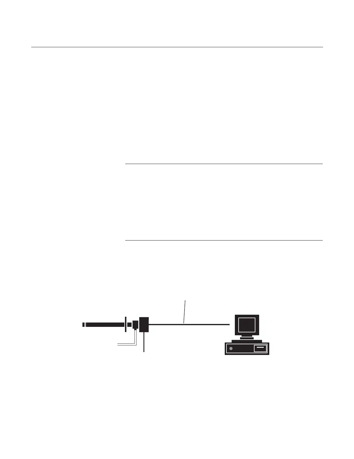
Figure 1-5. Hazardous Area
Oxymitter 5000 FOUNDATION
Fieldbus Connections
38740001
FieldbusDigital
Signal
2CalibrationGasLines
byCustomer
[90m(300ft)max]
FieldbusComputer
Terminal
LineVoltage
Hazardous Area
Oxymitter5000
withIntegralElectronics