Instruction Manual
IM-106-350C, Rev 2.2
July 2008
1-9
Hazardous Area Oxymitter 5000
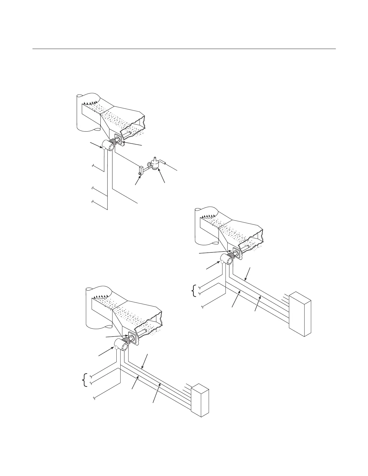
Figure 1-6. Typical System
Installation – Oxymitter 5000
with Integral Electronics
Oxymitter
5000
SPS 4001B
Reference
Air
Logic I/O
Calibration Gas
Adapter Plate
Stack
Duct
Gases
Calibration Gas 1
Calibration Gas 2
Inst. Air Supply
Line Voltage
FieldbusDigital
Signal
38740069
Duct
Stack
Gases
Calibration
Gas
Adapter
Plate
Line
Voltage
Logic I/O
Instrument
Air Supply
(Reference Air)
Pressure
Regulator
Flowmeter
STANDARD
Oxymitter
5000
FieldbusDigital
Signal
*Note: The IMPS 4000 or SPS 4001B must
be installed in a non-hazardous,
explosive-free environment.
Oxymitter
5000
IMPS 4000*
MULTIPROBE
AUTOCALIBRATION
OPTION
IMPS 4000
Reference
Air
Logic I/O
Calibration
Gas
Adapter
Plate
Stack
Duct
Gases
Calibration Gas 1
Calibration Gas 2
Inst. Air Supply
Line
Voltage
Fieldbus
DigitalSignal
SPS 4001B* SINGLE PROBE
AUTOCALIBRATION OPTION
(WITH REFERENCE AIR OPTION)