BRP-Rotax
INSTALLATION MANUAL
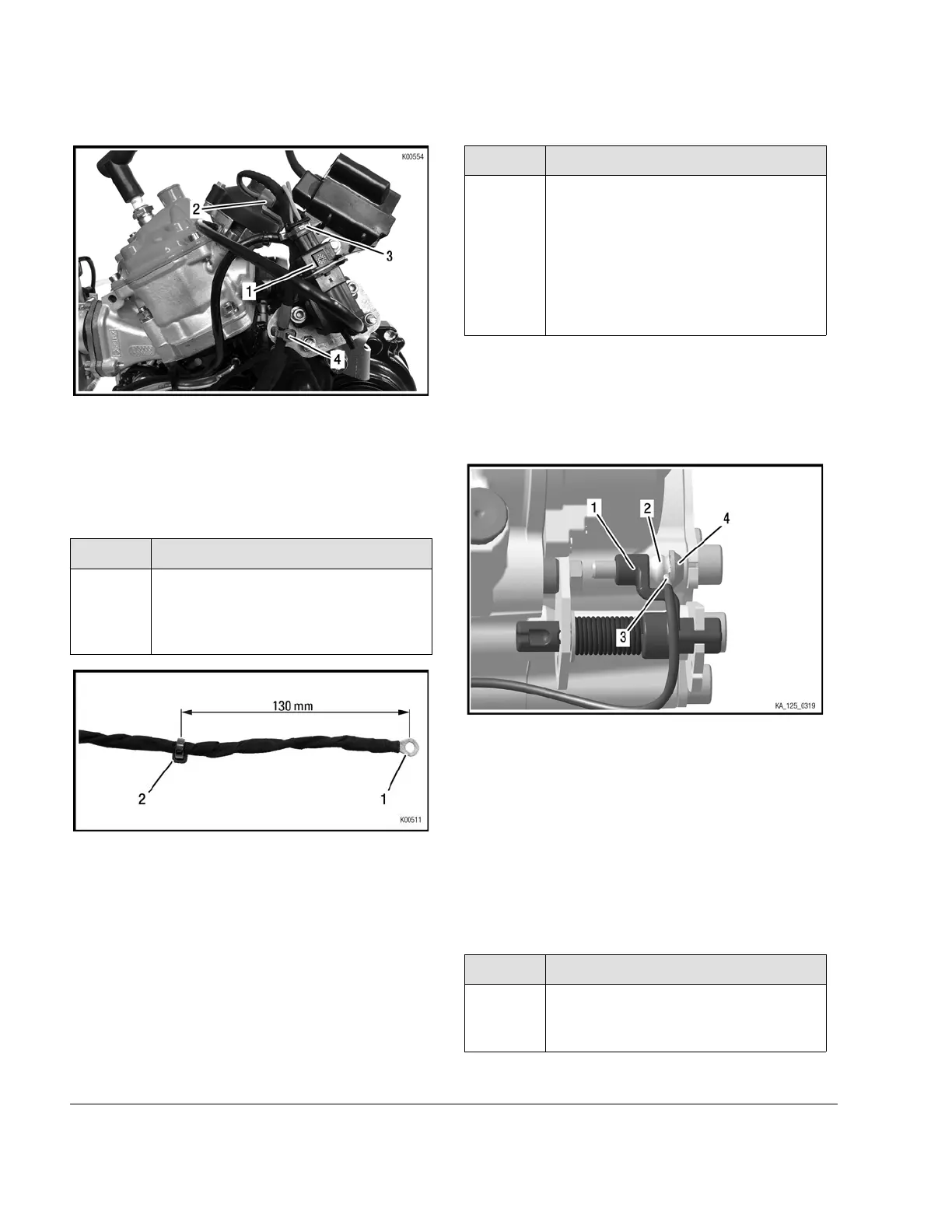
Figure 4.11
1 Solenoid valve
2
Ignition coil
3
Connectors (signed
green)
4
Cable tie
Step
Procedure
5
Remove isolation tape from the shift
contact wire (pos. 1) and loosely fas-
ten with a tie wrap (pos. 2) (about 130
mm from the cable lug).
Figure 4.12
1 Contact wire
2
Tie wrap
NOTE
Do not tighten tie wrap yet in order to be able to
change its position later on.
Step
Procedure
6
Fasten the cable lug (pos. 3) to the
shift contact assy. using the Plastite
screw M6x25 (pos. 4). Pay attention to
correct sequence of the components!
See following Figures.
For correct adjusting of the plastite
screw find the according section inside
the latest Operators Manual.
NOTE
Fasten the cable lug (pos. 3) between the fuel
tube 8 mm (pos. 2) and the Plastite screw
M6x25 (pos. 4). See following Figure.
Figure 4.13
1
Shift contact assy.
2
Fuel tube
3
Cable lug
4
Plastite screw M6x25
NOTE
The correct adjustment of the shift contact is de-
scribed in the Operators Manual, section “Ad-
justment of gear shifting”.
Step
Procedure
7
Fasten the wire of the shift contact
assy. with a tie wrap (pos. 1) on the
bottom of the engine.
3
Page 8
Edition: September 01 2019
Effectivity: 125 MAX DD2 evo

 Loading...


