5.1 IQT Actuators
The IQT range of actuators are suitable
for part turn applications requiring up
to 60 starts per hour.
5.2 IQTM Actuators
The IQTM range of actuators are
suitable for modulating control
duty of up to 1200 starts per hour
in accordance with IEC 34-1 to S4
50%. Commissioning of IQTM range
actuators is identical to the standard
IQT (refer to Sections 7, 8 and 9).
5.3 IQTF Actuators
The IQTF range of actuators are suitable
for part-turn and multi-turn, non-thrust
applications requiring low speed and
low operating turns. Commissioning
of IQTF range actuators is similar to
the standard IQT (refer to Sections 7,
8 and 9).
5.4 Lifting the Actuator
(Refer to Weights and Measures page
80 for actuator weight.)
Ensure the valve is secure before fitting
the actuator, as the combination may
be top heavy and therefore unstable.
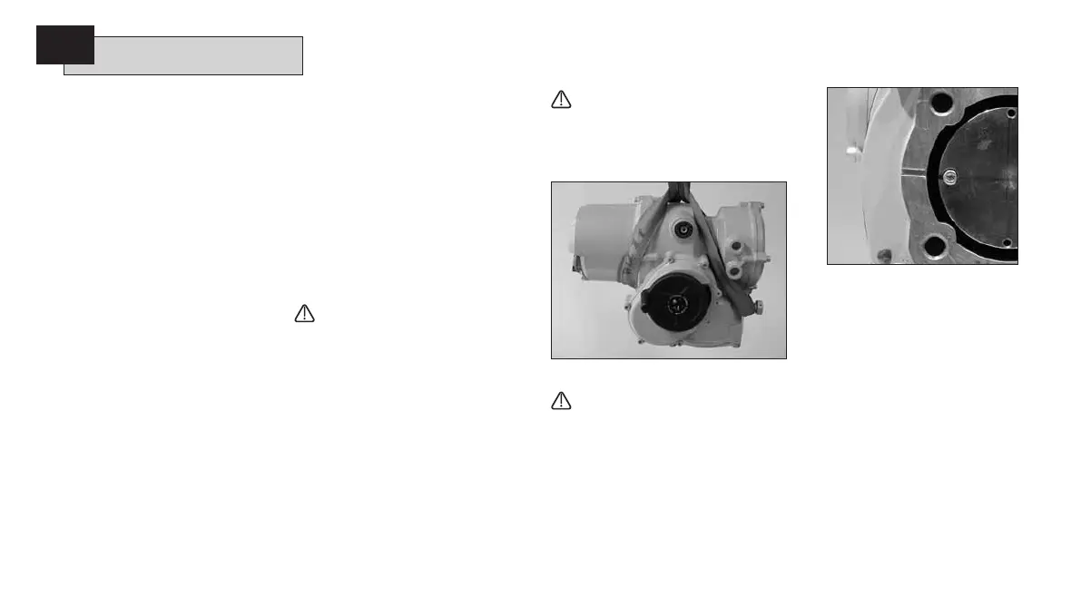
If it is necessary to lift the actuator
using mechanical lifting equipment
certified slings should be attached
as indicated in Figure 5. At all times
trained and experienced personnel
should ensure safe lifting, particularly
when mounting actuators.
WARNING:
Do not lift the actuator by the
handwheel.
A suitable mounting flange conforming
to ISO 5210 or USA Standard MSS
SP101 must be fitted to the valve.
Actuator to valve fixing must conform
to; Material Specification ISO Class 8.8,
yield strength 628 N/sq mm.
WARNING:
Do not lift the actuator and valve
combination via the actuator.
Always lift the valve/actuator
assembly via the valve.
Fig. 5
WARNING:
The actuator should be fully
supported until full valve stem
engagement is achieved and the
actuator is secured to the valve
flange.
Fig. 5.1
5.5 Securing Actuator to Valve
Before engagement ensure that the
actuator and valve are in the same
position (i.e. closed) and the drive bush-
machining matches the stem position.
Actuator position can be determined
using the display (refer to section 3.3
page 4) and if necessary can be moved
using the handwheel (refer to section
3.1 page 3). It may be necessary to
adjust the stop bolts to enable sufficient
travel. Refer to section 5.6 page 9.
8
Mounting the Actuator
5

 Loading...