3.4 Display Status Indication
– Travel
The IQT display provides real time
status indication. The top line of the
text display is reserved for travel status
indication. Fig 3.6 shows the travel
status example
Closed Limit
.
Fig. 3.6
Available travel status conditions displayed:
•
Closed Limit
Actuator has reached the
set closed limit position.
•
Open Limit
Actuator has reached the
set open limit position.
•
Moving Open
Actuator is traveling in
the open direction.
•
Moving Closed
Actuator is traveling in
the closed direction.
•
Stopped
Actuator has stopped in a
mid travel position, indicated in the
top display (%open).
•
Timer Active
Interrupter Timer option
enabled only. Interrupter Timer has
stopped the actuator mid travel for a
period equal to the set Timer Off
time. Refer to 9.13 page 55.
3.5 Display Status Indication
– Control
The bottom line of the text display is
reserved for control status indication
and is displayed for approximately 2
seconds after the control mode or
signal is applied. Fig 3.7 shows the
control status example
Remote Control
.
Fig. 3.7
Available control status conditions displayed:
•
Local Control
Local control selected -
red selector.
•
Local Stop
Local stop selected – red
selector.
•
Remote Control
Remote control
selected – red selector.
•
Local Close
Local close signal applied
– black selector.
•
Local Open
Local open signal applied
– black selector.
•
Remote Close
Remote close
(hardwired
or analogue) signal applied.
•
Remote Open
Remote open
(hardwired
or analogue) signal applied.
•
Remote ESD
Remote hardwired
emergency shut down signal applied.
•
Remote Bus Open
Remote Bus * open
signal applied.
•
Remote Bus Close
Remote Bus* signal
applied.
•
Remote Bus ESD
Remote Bus*
emergency shut down signal applied.
* Bus Control option fitted may be
Pakscan, Profibus, Modbus,
DeviceNet or Foundation Fieldbus.
Refer to actuator wiring diagram.
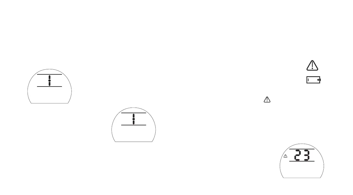
3.6 Display Alarm Indication
The IQT display provides alarm indication
in the form of text and alarm icons.
There are 2 alarm icons:
General Alarm:
Battery Alarm:
General Alarm
The general alarm icon will be
supported with text in the bottom line
indicating the particular alarm, or if
more than one is present, each alarm
will be displayed in sequence.
Fig 3.8 shows the status example
TORQUE TRIP CL
.
Fig. 3.8
5
Closed Limit
Closed Limit
Remote Control
Stopped
TORQUE TRIP CL

 Loading...