67
Heading
AA11
Maintenance, Monitoring
and Troubleshooting
Maintenance
Every Rotork actuator has been fully
tested before dispatch to give years of
trouble-free operation providing it is
installed, sealed and commissioned in
accordance with the instructions given
in this publication.
The IQT actuator’s unique double
sealed, non-intrusive enclosure provides
complete protection for the actuator
components.
Covers should not be removed for
routine inspection as this may be
detrimental to the future reliability of
the actuator.
The electrical control module cover is
bonded by the Rotork quality control
seal. It should not be removed as the
module contains no site-serviceable
components.
All electrical power supplies to the
actuator must be isolated before any
maintenance or inspection is carried
out, except replacement of the battery.
Electrical supplies must be isolated
before actuator covers are removed
refer to Battery replacement
instructions.
Routine maintenance should include
the following:
* Check actuator to valve fixing bolts
for tightness.
* Ensure valve stems and drive nuts are
clean and properly lubricated.
* If the motorised valve is rarely
operated, a routine operating
schedule should be set up.
* Replace actuator battery every
5 years.
* Check the actuator enclosure for
damage, loose or missing fasteners.
* Ensure there is not an excessive
build up of dust or contaminant
on the actuator.
* Check for any loss of lubricant.
The Actuator Battery
The battery supports the actuator
position updating circuits and the
position (LCD) display when the main
power supply is turned off. It ensures
the current position is updated and
displayed when manual operation takes
place with the main power turned off.
The battery is not required to retain any
actuator settings.
WARNING:
The battery holder in the actuator
gearcase also protects the user from
the hazardous live connections
inside the actuator and therefore it
must not be damaged. The actuator
must be isolated or disconnected
if the battery holder has to
be removed from the actuator
gearcase.
A unique circuit has been incorporated
into the battery function of the IQT,
effectively reducing the overall drain
and significantly increasing the battery
life.
In normal circumstances
battery replacement interval should
not exceed 5 years. Ambient
temperature and plant operating
conditions may affect battery life.
Battery level status is indicated by an
icon on the actuator display, refer to
Section 3.4 Alarm Indication (refer to
page 5).
If the battery icon is displayed the
battery must be replaced.
Battery Replacement
If the actuator is located within a
hazardous area permission must be
obtained in the form of a ‘‘hot work
permit’’ or other local regulation before
removal and/or replacement of the
battery.
Removal of the battery with the main
electrical power switched off will result
in stored Datalogger records time
reference being lost for the duration
when there is no mains and battery
power. It is therefore recommended
that the battery is replaced with the
main electrical supply to the actuator
switched on.
If main electrical power is not available
or if main power has been switched off
while the battery was discharged, it is
recommended that the actuator limits
be checked after battery replacement
(refer to Section 8 Commissioning Basic
Settings, page 17).
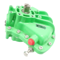
Battery Removal
The actuator must be selected to Stop
using the red selector (refer to page 3).
Access to the battery is via a labelled
sealing plug situated on the main
gearcase near the handwheel hub.

 Loading...