WARNING:
Ensure all power supplies
are isolated before removing
actuator covers.
Check that the supply voltage agrees
with that stamped on actuator
nameplate.
A switch or circuit breaker must be
included in the wiring installation of
the actuator. The switch or circuit
breaker shall be mounted as close
to the actuator as possible and shall
be marked to indicate that it is the
disconnecting device for that particular
actuator. The actuator must be
protected with overcurrent protection
devices rated in accordance with
Rotork publication No. E135E Electric
motor performance data for IQT range
actuators.
WARNING:
Actuators for use on phase to
phase voltages greater than 600V
A.C.must not be used on supply
systems such as floating, or earth-
phase systems, where phase to
earth voltages in excess of 600V
A.C. could exist.
6.1 Earth/Ground Connections
A lug with a 6mm diameter hole is
cast adjacent to the conduit entries for
attachment of an external protective
earthing strap by a nut and bolt. An
internal earth terminal is also provided,
however it must not be used alone as
the protective Earth Connection.
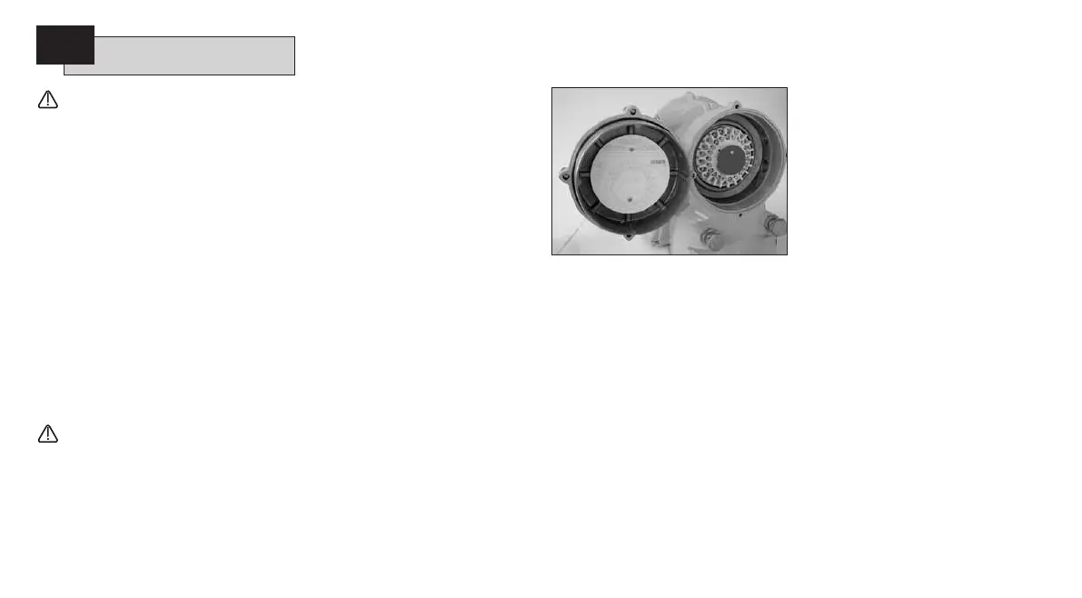
6.2 Removing Terminal Cover
Using a 6mm Allen key loosen the four
captive screws evenly. Do not attempt
to lever off the cover with a screwdriver
as this will damage the “O” ring seal
and may damage the flamepath on a
certified unit.
Actuators containing a Setting Tool
fitted to the inside of the terminal
compartment cover are identified with
a self-adhesive yellow label on the
outside of the terminal compartment
cover.
The wiring code card fixed in the cover
is particular to each actuator and must
not be interchanged with any other
actuator. If in doubt check the serial
number on the code card with that of
the actuator.
Fig. 6
A plastic bag in the terminal
compartment contains: Terminal screws
and washers, spare cover “O” ring
seal,wiring diagram and instruction
book.
6.3 Cable Entry
Only appropriate certified Explosion-
Proof entry reducers, glands or conduit
may be used in hazardous locations.
Remove red plastic transit plugs. Make
cable entries appropriate to the cable
type and size. Ensure that threaded
adaptors, cable glands or conduit
are tight and fully waterproof. Seal
unused cable entries with a steel or
brass threaded plug. In hazardous areas
an appropriately certified threaded
blanking plug must be used.
The cable entries on the actuator
terminal housing are tapped M25
x 1.5p.
6.4 Connecting to Terminals
On EExde enclosure units connections
to the power and control terminals
must be made using AMP type 160292
ring tabs for power and earth terminals
and AMP type 34148 ring tabs for the
control terminals.
Refer to the wiring diagram inside the
terminal cover to identify functions of
terminals. Check that supply voltage
is the same as that marked on the
actuator nameplate.
Remove power terminal screen.
Begin by connecting these cables and
replace screen.
When all connections are made ensure
wiring diagram is replaced in the
terminal compartment.
6.5 Replacing Terminal Cover
Ensure cover “O” ring seal and spigot
joint are in good condition and lightly
greased before re-fitting cover.
10
Cable Connections
6

 Loading...