12
Commissioning continued
7
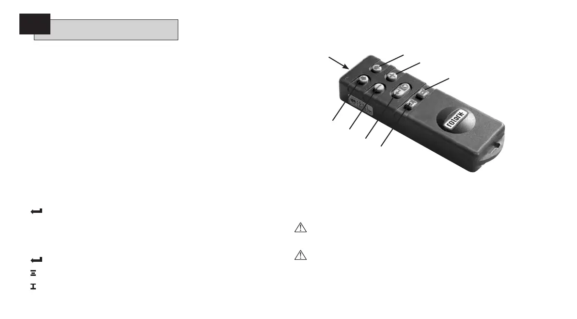
7.2 The Setting Tool (old version)
Specification
Enclosure IP67
Certification EEx ia IIC T4 (intrinsically safe)
FM, INT SAFE, Class I & II Div 1 Groups A B C D E F G, T4A
CSA, Exia, Class I, II Div 1 Groups A B C D
Power supply 9V Battery (supplied and fitted)
Operating range 0.75m (from actuator display window)
Name Instruction
1. m
Key* Display next function down
2.
k
Key* Display next function across
3.
-
Key Decrease/change displayed function’s value or option setting
4.
+
Key Increase/change displayed function’s value or option setting
5.
Key Enter displayed value or option setting
* Pressing the two arrow keys together returns the actuator display to the position
indication mode
Infra-red local operation (when enabled)
5.
Key Stop actuator
6.
Key Open actuator
7.
Key Close actuator
8. Infra-red Transmitter Window
Fig. 7.1 The Setting Tool
Setting Tool Battery Replacement
Battery status can be checked by looking at the Infra-red transmitter window while
depressing any Setting Tool button. A flashing red indicator should be seen.
Battery replacement must be carried out in a safe area. To replace
the battery remove the six caphead screws in the back of the Setting Tool.
Remove the back cover to expose the battery.
In order to maintain hazardous area certification fit only Duracell
MN1604 or Rayovac Alkaline Maximum NoAL-9V battery types. Refit cover
ensuring red indicator LED faces the transmitter window in the back cover.
When a button is depressed the Setting Tool transmits the relevant instruction
to the actuator by infra-red pulses and must therefore be directly in front of the
actuator indicator window and at a distance no greater than 0.75m.
8
2
4
6
7
5
3
1
 Loading...