2015-2017 5.0L Mustang Phase 1/2 RHD ROUSHcharger Kit
SECTION E – FINAL ASSEMBLY
1316-RHD-AA 12152016 78 800.59.ROUSH
SECTION E – FINAL ASSEMBLY
1. Fill the engine cooling system (using a proper
coolant mixture) to the marked level on the
radiator degas bottle.
2. Using the same coolant mixture, ll the intercooler
system. The coolant should be approximately
one inch below the top of the cap.
IMPORTANT: Both coolant systems can trap
a large amount of air. It is very important to
verify that the air is purged and that coolant is
fl owing properly through both systems. ROUSH
recommends vacuum fi lling both systems to
properly evacuate the trapped air.
3. Reinstall lower close-out panel and inner fenders
by reversing the removal procedures.
4. Reinstall the front wheels/tires. Torque wheel lugs
to the factory Ford speci cations.
5. Inspect all underhood wiring harnesses for
potential interference issues. Use zip ties to
safely position the harness away from any areas
of concern.
6. Reinstall the radiator trim cover by reversing the
removal instructions.
7. If the PCM was removed and shipped to ROUSH
for a ROUSH performed ash, reinstall it once
the PCM is returned from ROUSH. If you are
equipped with a SAE J2534 pass through device,
refer to the PCM Flashing instructions found on
our website when the installation is complete.
DO NOT ATTEMPT TO REINSTALL THE PCM
AND START THE VEHICLE IF THE PCM IS NOT
EQUIPPED WITH A ROUSH CALIBRATION.
OPERATING THE ENGINE WITHOUT THE
RECALIBRATED PCM WILL RESULT IN
ENGINE DAMAGE OR FAILURE AND WILL
VOID THE WARRANTY.
8. Reinstall the battery connections by connecting
the positive cable rst then connecting the
negative cable. Reinstall the battery cover panel
with pushpins.
9. Reconnect the fuel pump control module
electrical connector located under the backseat
on the driver side.
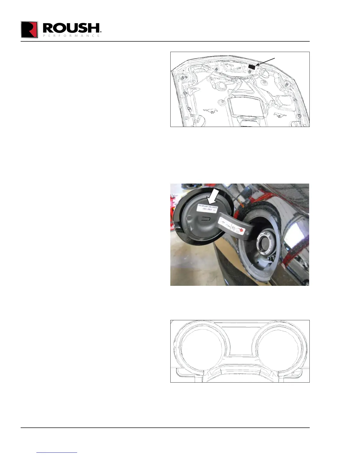
10. Place the Belt Routing Diagram (13116E072)
found in Hardware Kit F (1315-TVSHKF) on
the underside of the hood, on the driver side,
opposite of the factory Vehicle Emission Control
Information decal.
11. Place the PCM Decal (R07100008) found in
Hardware Kit F (1315-TVSHKF) in a visible
location.
12. Place the “PREMIUM FUEL ONLY” Decal
(13109A095) (white decal with black lettering)
found in Hardware Kit F (1315-TVSHKF) on the
arm door of the fuel ller door as shown.
13. Place the “PREMIUM FUEL” (R07110004) Clear
Decal with white lettering on the instrument
cluster bezel, on the at area below the small
center gauges as shown.
14. Place the E.O. decal (D41826-9A025EO) in a
visible location under the hood. (Top of airbox lid
or side of strut tower.)
PLACE DECAL
IN THIS AREA
PLACE DECAL HERE