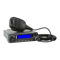
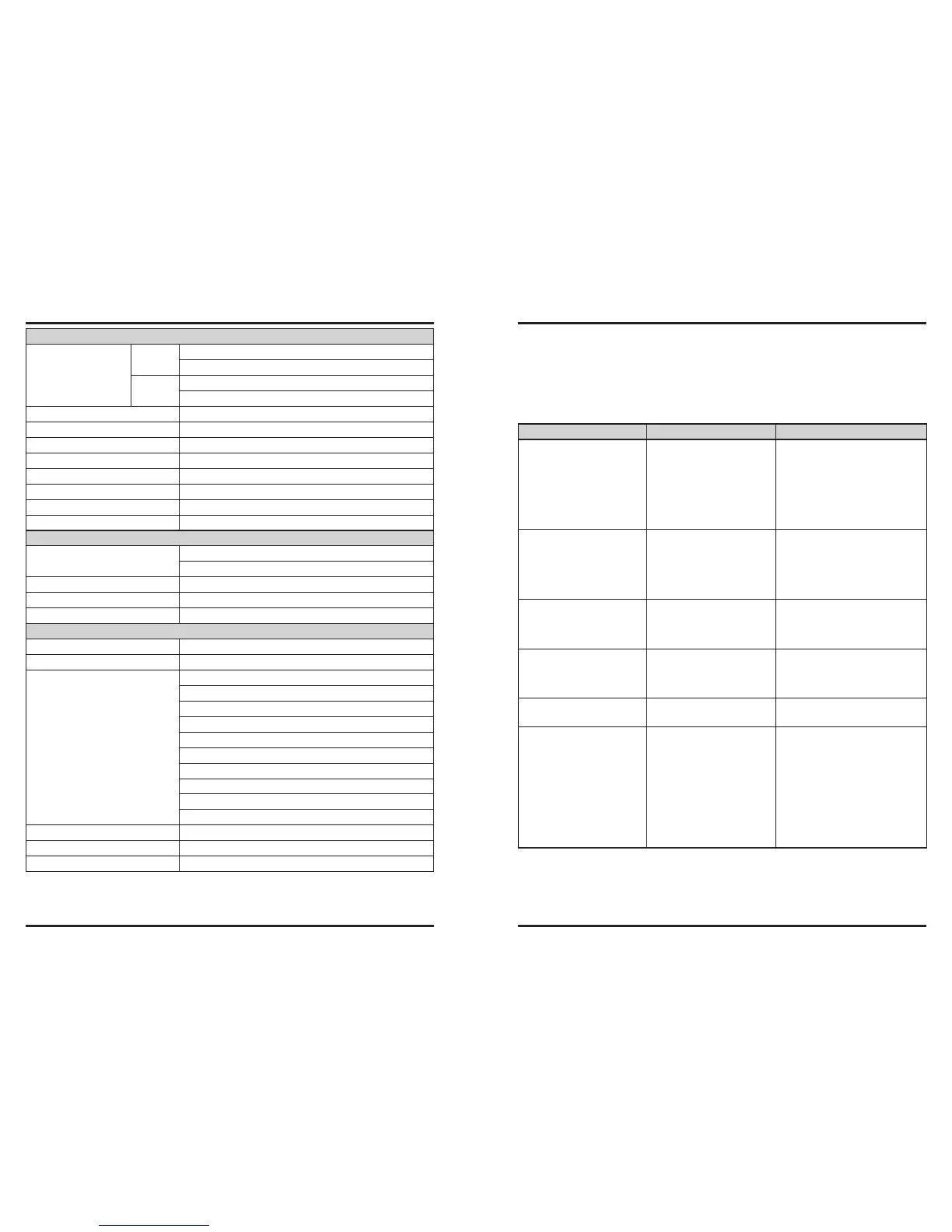
GENERAL SPECIFICATION
Frequency Range
RX
108.000-520.000 MHz
700.000-999.990 MHz
TX
136.000-174.000 MHz
400.000-470.000 MHz
Channel Step 5/10/12.5/15/20/25/50/100kHz
Modes of Emission F3E, F2D, F2A
Antenna Impedance 50Ohms,unbalanced(Antenna Duplexer built-in)
Frequency Stability ±5 ppm (–10 °C ~ +60 °C)
Supply Voltage 13.8 VDC (±15 %), negative ground
Operating Temperature Range –20 °C ~ +60 °C
Dimensions(W x H x D) 140× 42× 168mm(W/O Knobs)
Weight(Approx.) 1kg
TRANSMITTER
Output Power
50/20/10/5 W (144 MHz)
45/20/10/5 W (430 MHz)
Maximum Deviation ±5 kHz, ±2.5 kHz
Spurious Impedance At least -60dB below
Microphone Impedance 2kΩ
RECEIVER
Circuit Type Double-conversion superheterodyne
Intermidiate Frequencies 45.05 MHz/450 kHz
Sensitivity
0.8 μV (TYP) for 10 dB SN (108 - 137 MHz, AM)
0.2 μV for 12 dB SINAD (137 - 150 MHz, FM)
0.25 μV for 12 dB SINAD (150 - 174 MHz, FM)
0.3 μV (TYP) for 12 dB SINAD (174 - 222 MHz, FM)
0.25 μV (TYP) for 12 dB SINAD (222 - 300 MHz, FM)
0.8 μV (TYP) for 10 dB SN (300 - 336 MHz, AM)
0.25 μV for 12 dB SINAD (336 - 420 MHz, FM)
0.2 μV for 12 dB SINAD (420 - 520 MHz, FM)
0.4 μV (TYP) for 12 dB SINAD (800 - 900 MHz, FM)
0.8 μV (TYP) for 12 dB SINAD (900 - 999.99 MHz, FM)
Selectivity 12KHz/30KHz
Maximum AF Output 2 W @ 8 Ω for 10% THD
AF Output Impedance 4-16Ω
The problems described in the following tables are commonly encountered operational
malfunctions. These types of difculties are usually caused by improper hook-up, acci-
dental incorrect control settings, or operator error due to incomplete programming. These
problems are usually not caused by circuit failure. Please review these tables and the ap-
propriate section(s) of this instruction manualbefore assuming your transceiver is defec-
tive.
Problem Probable Cause Corrective Action
The transceiver will not
power up after connecting
a 13.8V DC power supply
and pressing the PWR key.
Nothing appears on the dis-
play
1. The power cable was con-
nected backwards.
2. One or more of the power
cable fuses disconnect.
1. Connect the supplied DC power
cable correctly: Red- (+); Black
- (–).
2. Look for the cause of the blown
fuse(s). After inspecting and
correcting any problems,install
a new fuse(s) with the same
ratings (15A).
The display is too dim, even
though you selected a high
brightness level
The supply voltage is too low The supply voltage requirement is
13.8 V DC ±15% (11.7 V to 15.8 V
DC).If the input voltage is outside
this range, adjust your regulated
power supply and/or check all
power cable connections
The frequency cannot be
selected by turning the DIAL
knob control or by pressing
Mic [UP]/[DWN].
Memory Recall was selected Press [V/M] key to switch to the
VFO mode.
Memory Channels cannot
be selected by turning the
DIAL knob or by pressing
Mic [UP]/[DWN].
No data has been stored in
any Memory Channels.
Store data in some Memory Chan-
nels
Most of the keys on the MIC
don’t work.
The keypad is locked. Unlock the keypad.
You cannot transmit even
though you press Mic [PTT].
1. The microphone plug was
not inserted completely
into the front panel con-
nector.
2. You selected a transmit
offset that places the
transmit frequency outside
the allowable transmit fre-
quency range.
1. Switch OFF the power, then
insert the microphone plug until
the locking tab clicks in Place.
2. Retransmit the frequency devia-
tion, to match the Tx frequency
range. Press [SET] to enter the
menu mode, turn the HOME
Dial knob,select menu #36,
press the HOME dial knob,
then turn it to select the right
frequency deviation.