B
ASE
S
TATION
I
NSTALLATION
The transceiver is ideal for base station use as well as in mobile installations. The trans-
ceiver is specically designed to integrate into your station easily, using the information
to follow as a reference.
AC Power Supplies
Operation of this transceiver from an AC line requires a power source capable of provid-
ing at least 10 Amps continuously at 13.8 Volts DC. The
FP-1023
and
FP-1030A
AC
Power Supplies are available from your dealer to satisfy these requirements. Other well-
regulated power supplies may be used, as well, if they meet the above voltage and current
specications.
Use the DC power cable supplied with your transceiver for making power connections to
the power supply. Connect the
RED
power cable lead to the POSITIVE (+) power supply
terminal, and connect the
BLACK
power cable lead to the NEGATIVE (–) power supply
terminal.
Packet Radio Terminal Node Controller (TNC)
The transceiver provides a convenient rear-panel DATA jack for easy connections to your
TNC. This connector is a standard mini-DIN connector. A pre-wired connector and cable
assembly option, model
CT-39A
, is available from your local dealer.
The transceiver’s
DATA
jack connections are optimized for the data transmission and re-
ception speed in use. In accordance with industry standards, the signal levels, impedanc-
es, and bandwidths are signicantly different on 9600 bps as opposed to 1200 bps. If your
TNC does not provide multiple lines to accommodate such optimization, you may still be
able to utilize your TNC, if it is designed for multiple-radio use, by connecting the TNC
“Radio 1” port to the 1200 bps lines on the TRANSCEIVER, and the “Radio 2” port to
the 9600 bps lines.
The pin connections of the Data connector are shown below.
Pin Label Note CT-39A Wire Color
1
PKD
(DATA IN)
Packet Data Input
Impedance: 10 kΩ,
Maximum Input Level: 40 mV p-p for 1200 bps
2.0 Vp-p for 9600 bps
Brown
2 GND Signal Ground Red
3 PTT Gound to Transmit Orange
4 RX9600
9600 bps Packet Data Output
Impedance: 10 kΩ, Maximum Output: 500 mV p-p
Yellow
5 RX1200
1200 bps Packet Data Output
Impedance: 10 kΩ, Maximum Output: 300 mV p-p
Green
6
PKS
(SQL)
Squelch Control
Squelch Open: +5 V, Squelch Close: 0 V
Blue
B
ASE
S
TATION
I
NSTALLATION
Note that 9600 bps packet transmit-deviation adjustment is very critical to successful opera-
tion, and can only be accomplished using a calibrated deviation meter (such as that found on
an FM Service Monitor used in a communications service center). In most cases, the Packet
Data Input level (set via a potentiometer inside the TNC) must be adjusted to provide a devi-
ation of ±2.75 kHz (±0.25 kHz). Check with your packet node’s sysop if you have any ques-
tions about the appropriate deviation level for your network. Note also that high throughput
on 9600 bps frequently requires strong signals, so you may wish to consider the use of a
directional antenna such as a Yagi for communication with high-speed packet nodes.
The setting of the 1200 bps Packet Data Input level is much less critical than it is at 9600 bps,
and satisfactory adjustment to the optimum (±2.5 ~ ±3.5 kHz) deviation can usually be done
“by ear” by adjusting the TNC’s 1200 bps TX Audio Level potentiometer so that the outgo-
ing packets (as monitored on a separate VHF or UHF receiver) are approximately the same
level as (A) the DTMF tones or (B) the 1750 Hz Burst tone produced using the microphone.
Finally, note that the Menu (“Set”) mode allows you to set the Packet data rate (1200 or
9600 bps) independently for each band. If you have trouble getting your TRANSCEIVER
to respond correctly during packet operation, check to be certain that you do not have
Menu #26 (
P K T.S P D
) set to the wrong data rate.
You may activate the microphone input while operating on the packet mode via the Menu
#25 (
P K T.MI C
), if desired. Generally, we do not recommend this, as a “live” micro-
phone’s audio input will tend to reduce throughput by interfering with the packets being
transmitted by your radio.
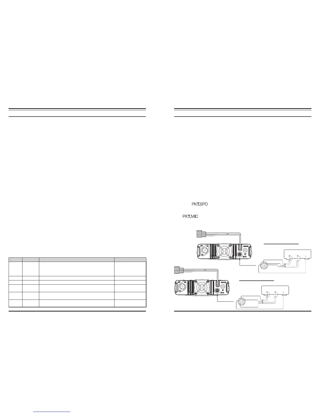
9600 BPS PACKET SETUP
1200 BPS PACKET SETUP
DATA
OUT
DATA
IN PTT
PTT
GND
DATA IN
DATA OUT
(960 0b ps )
DATA
OUT
DATA
IN PTT