M
OBILE
I
NSTALLATION
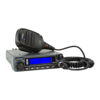
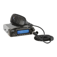
This transceiver must only be installed in vehicles having a 13.8 Volt negative ground
electrical system. Mount the transceiver where the display, controls, and microphone are
easily accessible, using the supplied mounting bracket.
The transceiver may be installed in almost any location, but should not be positioned near
a heating vent nor anywhere where it might interfere with driving (either visually or me-
chanically). Make sure to provide plenty of space on all sides of the transceiver so that air
can ow freely around the radio’s case. Refer to the diagrams showing proper installation
procedures.
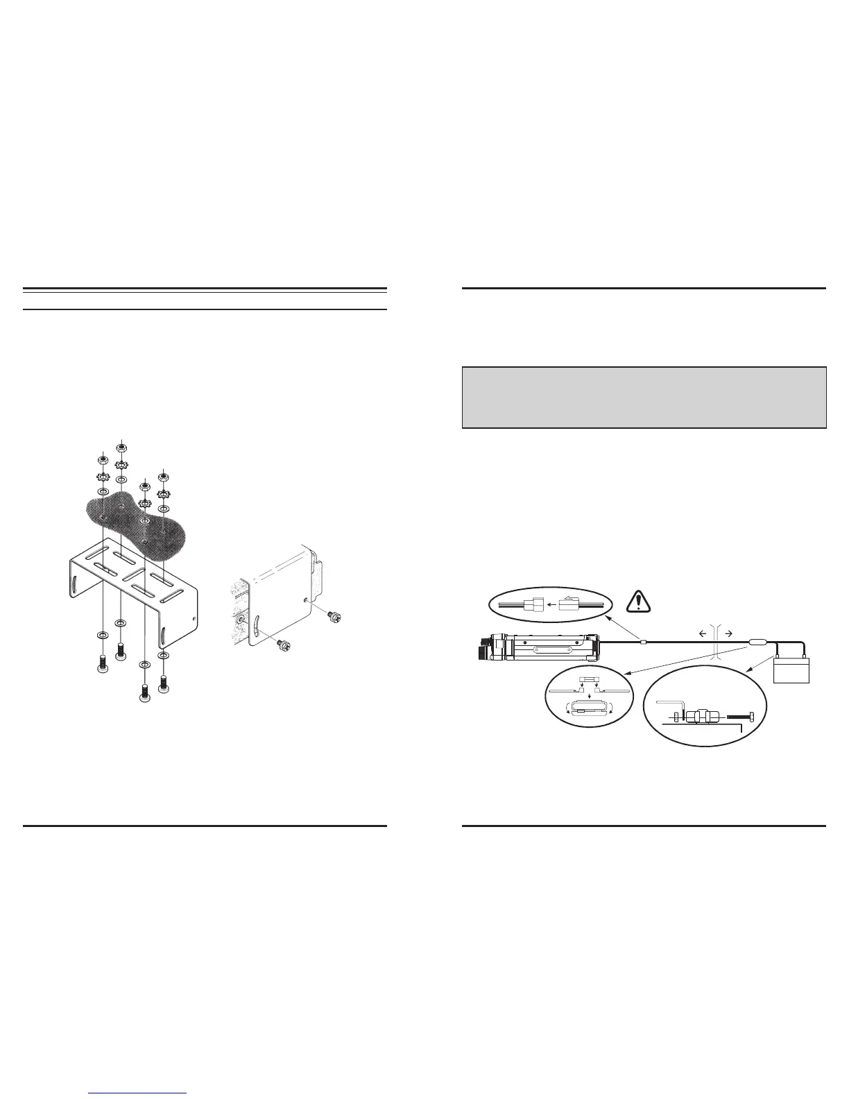
Mobile Power Connections
To minimize voltage drop and avoid blowing the vehicle’s fuses, connect the supplied DC
power cable directly to the battery terminals. Do not attempt to defeat or bypass the DC
cable’s fuse - it is there to protect you, your transceiver, and your vehicle’s electrical
system.
Warining!
Never apply AC power to the power cable of the transceiver, nor DC voltage great-
erthan 15.8 Volts. When replacing the fuse, only use a 15-A fast-blow type. Failure
to observe these safety precautions will void the Limited Warranty on this product.
Before connecting the transceiver, check the voltage at the battery terminals while
revving the engine. If the voltage exceeds 15 Volts, adjust the vehicle’s voltage regu-
lator before proceeding with installation.
Connect the
RED
power cable lead to the POSITIVE (+) battery terminal, and the
BLACK
power cable lead to the NEGATIVE (–) terminal. If you need to extend the
power cable, use #12 AWG or larger insulated, stranded copper wire. Solder the splice
connections carefully, and wrap the connections thoroughly with insulating electrical
tape.
Before connecting the cable to the transceiver, verify the voltage and polarity of the
voltage at the transceiver end of the DC cable using a DC voltmeter. Now connect the
transceiver to the DC cable.
Cabin Engine Room
Battery
RED: Positive (+)
BLACK: Negative (–)
WARNNING!
Never remove the FUSE holders
from the DC cable.
Mobile Speaker
The external speaker has the impedance of 4Ω, and can be compatible with 3W of the au-
dio ouput radio.