q
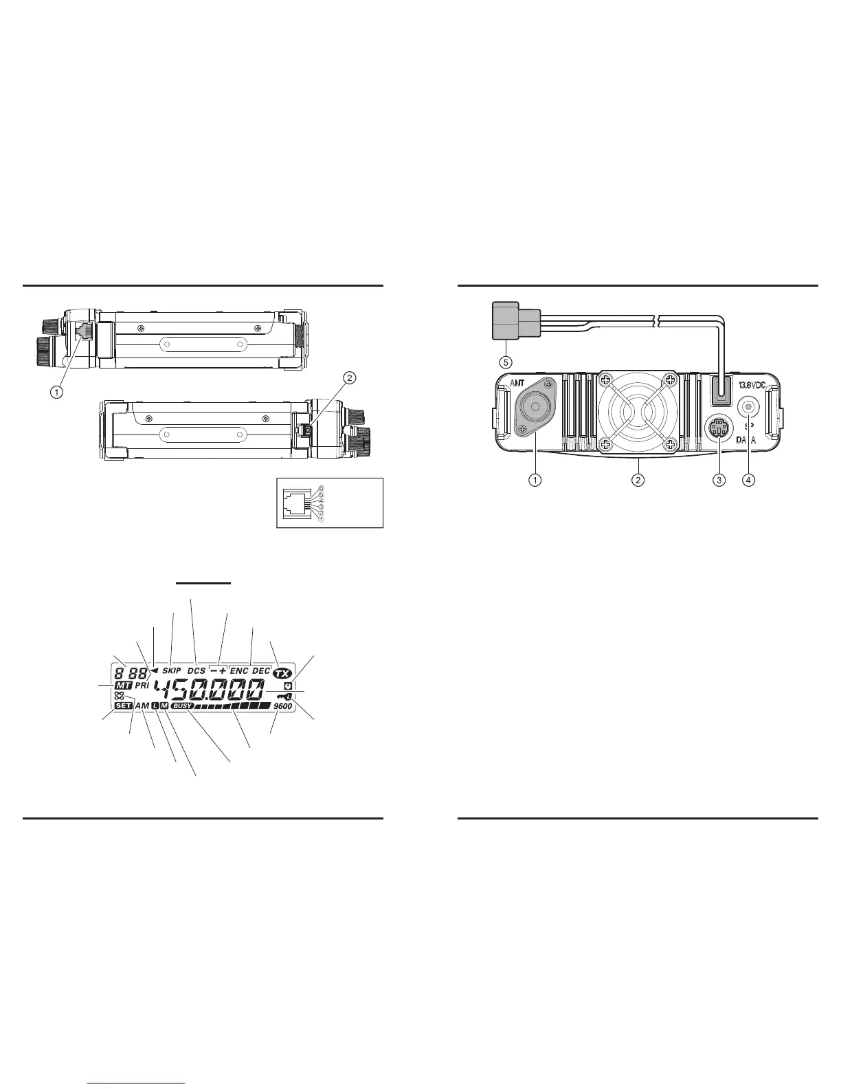
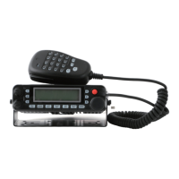
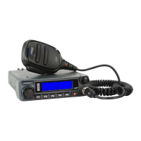
MIC Jack (Right Side)
Connect the supplied microphone to this jack.
w
Front Panel Release Knob (Left Side)
Press this knob to unlock the front panel to detachable the front panel from the trans-
ceiver’s main body for remote-head operation (requires Separation Kit).
Memory Channel Number
Skip Memory Channel
Preferential Memory Channel
Digital Code Squelch (DCS) Operation
CTCSS Operation
Repeater Shift Direction
Transmission in Progress
Automatic Power-Off Active
Keypad/DIAL Lock Active
9600 bps Packet Mode
S- & PO Meter
BUSY Channel (or Squelch Off)
ISPLAY
: PT T
: MI C
: GND
: +9V
: SW 1(Key Control)
: SW 2 (Key Contol)
q
ANT
Jack
Connect your antenna here, using a type-M plug (for USA version) or type-N plug (for
EXP version) and coaxial cable.
w
Cooling Fan
The cooling fan rotates during transmission, and for 30 seconds after the radio returns
to the receive mode after transmitting.
When the RF power amplier’s heat sink reaches a moderately high temperature, the
cooling fan will rotate automatically even if the radio is in the receive mode.
e
DATA
Jack
This 6-pin mini-DIN connector provides simple interfacing to a packet Terminal
Node Controller (TNC) for 1200 bps or 9600 bps operation.
r
EXT SP
Jack
This 2-conductor, 3.5-mm mini phone jack provides audio output for an optional
speaker. The optimum load impedance is 8 Ohms. Inserting a plug into this jack dis-
ables the audio path to the transceiver’s internal speaker.
t
13.8V DC
Cable Pigtails
This is the DC power supply connection for the transceiver. Use the supplied DC ca-
ble to connect this pigtail to the car battery or base station DC power supply capable
of at least 10 Amperes (continuous duty). Make certain that the Red lead connects
to the Positive (+) side of the power source, and that the Black lead connects to the
Negative (–) side of the power source.