VDR-100G2/G2S Operation User Manual 5
RUT-UM-02-002_Rev. 2.0
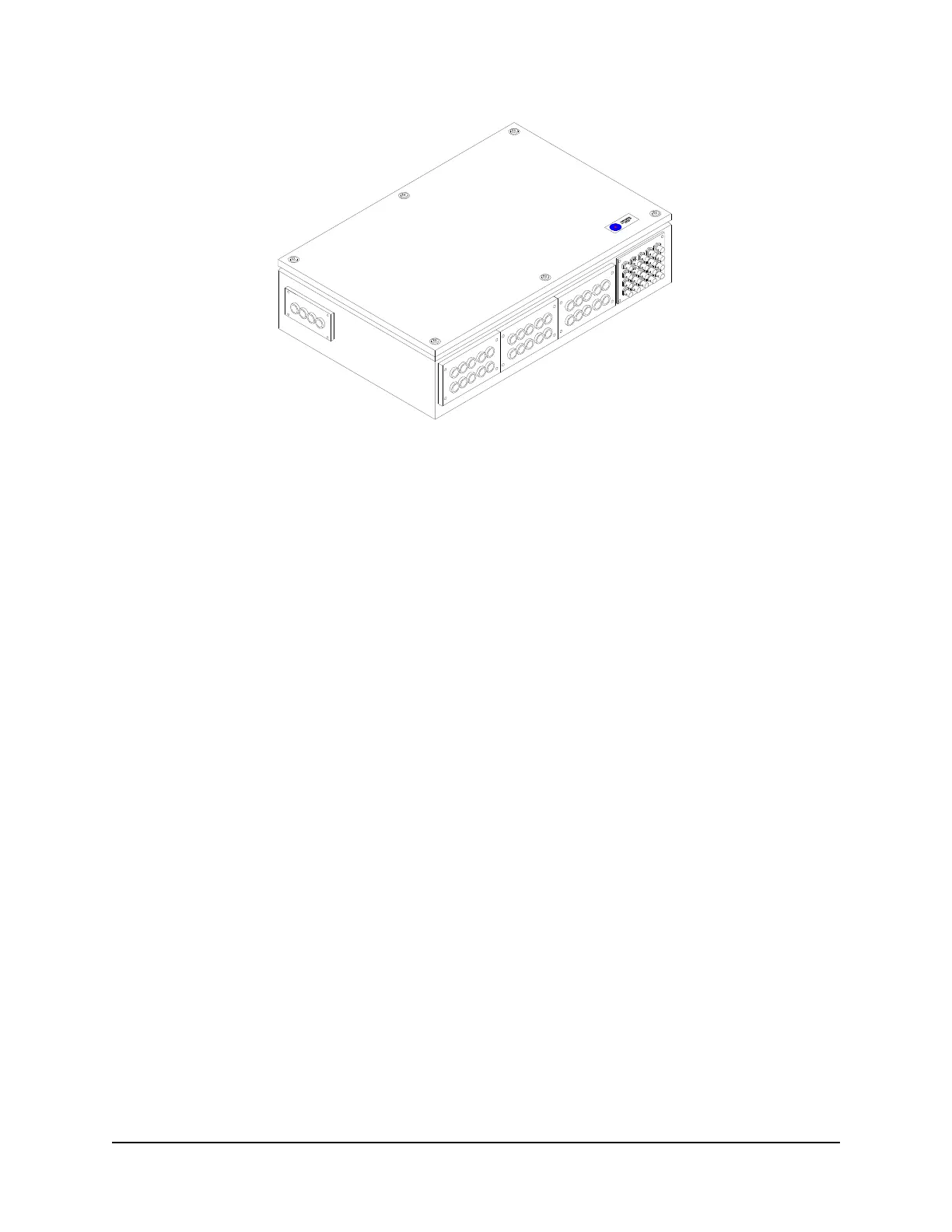
Figure 1-4 - Data Acquisition Unit
1.1.3 Audio Module
The Audio Module receives audio information from bridge microphones and vessel radios in accordance
with the IEC 61996 standard. All audio data is routed to the DMM for processing, storage, and eventual
retrieval. This module also controls the test buzzers used to verify the functionality of all microphones
connected to the VDR-100G2.
The standard Audio Module is an autonomous audio capture and broadcast device with eight (8) input
ports for capturing audio data from a combination of microphones or line level inputs. An example
combination may be:
Six (6) microphones
Transmitted and received signals from the primary VHF radio.
The module combines pairs of input signals, digitizes the combined audio channels, and outputs the
audio data through an Ethernet port. Twelve or sixteen input Audio Module units are also available for
capturing audio data from additional microphones or other sources.
Additional specifications:
The audio inputs are transformer coupled and can be configured on site as either microphone or
line level connections.
The 8, 12, or 16 audio inputs are mixed 2:1 (either LEFT/RIGHT for microphones, or TX/RX for
VHF) to produce 4, 6, or 8 single-ended digital signal streams respectively.
Separate level control potentiometers are located on the PCB, and can be adjusted using a
screwdriver. These levels are preset during manufacturing.
The audio signals are sampled to 12-bit resolution. The resulting digitized data stream is
broadcast across an Ethernet cable for storage.
The Audio Module Ethernet output is connected to a dedicated Ethernet port on the DMM.