VDR-100G2/G2S Operation User Manual 62
RUT-UM-02-002_Rev. 2.0
7.3 Corrective Maintenance
7.3.1 Alarm Code Descriptions
Listed below are the alarm codes that may appear on the OAU LCD display:
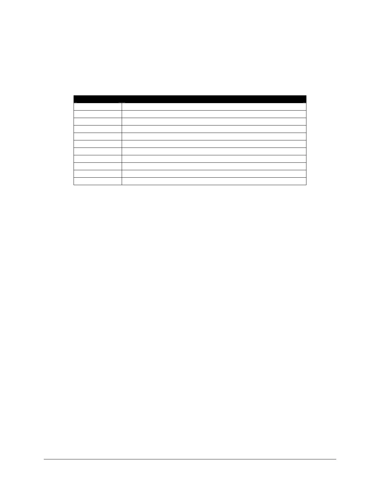
Alarm Code Description
System Error Communication with the Record Application has been lost
Video Error Communication with the Video Module has been lost
Audio Error Communication with the Audio Module has been lost
FRM Error Communication with the Final Recording Medium has been lost
Power Fail Loss of utility power
PCM Error Communication has been lost with the Power Control Module
Remote Error Communication has been lost with the Remote Storage Module
Serial Error Communication has been lost with the NMEA Module
Mic Error Communication has been lost with one of the microphones
Disk Error Failure to secure a data set
GPS Error Data is failing to record on TimeMuxID parameters entry
Table 7-1: Alarm Code Description
Pressing the “Mute” button acknowledges the alarm code and silences the alarm. The red alarm indicator
lamp will stay illuminated until all alarm conditions are cleared. If there is more than one alarm condition,
the OAU display will cycle through the current alarm messages.
SYSTEM ERROR: Turn the ship breaker for the VDR/SVDR power OFF. Wait 2 hours and 15 minutes.
Turn the VDR/SVDR power breaker back on and see if this has cleared the error. If error returns, get
service to find and repair the error.
VIDEO ERROR: Open Data Processing Unit (DPU) (the VDR/SVDR’s main cabinet) and ensure that the
2 AMP DC breaker inside marked Video/NMEA is closed. Make sure the Ethernet cable plugged into the
VDR/SVDR’s computer port marked Video/NMEA is pressed all the way into this port. There should be a
solid green link light and a flashing yellow light associated with this port. Locate the video module and
ensure it’s red LED power lights are lit and that its Ethernet cable is securely inserted in the modules
Ethernet port. If error returns, get service to find and repair the error.
AUDIO ERROR: Open Data Processing Unit (DPU) (the VDR/SVDR’s main cabinet) and ensure that the
2 AMP DC breaker inside marked Audio/Alarm is closed. Make sure the Ethernet cable plugged into the
VDR/SVDR’s computer port marked Audio is pressed all the way into this port. There should be a solid
green link light and a flashing yellow light associated with this port. Locate the audio module and ensure
it’s red LED power lights are lit and that its Ethernet cable is securely inserted in the modules Ethernet
port. If error returns, get service to find and repair the error.
FRM ERROR: Open Data Processing Unit (DPU) (the VDR/SVDR’s main cabinet) and ensure that the 2
AMP DC breaker inside marked FRM is closed. Make sure the Ethernet cable plugged into the
VDR/SVDR’s computer port marked FRM is pressed all the way into this port. There should be a solid
green link light and a flashing yellow light associated with this port. If problem still exists; open the FRM 2-
AMP breaker by pressing its Red Button, wait 5-seconds and close this breaker by pressing its Black and
White Button marked with the number 2. If error returns, get service to find and repair the error.
PCM ERROR: Open Data Processing Unit (DPU) (the VDR/SVDR’s main cabinet) and ensure that the
two serial connectors on the back of the computer are still firmly in place. If problem persists turn the ship
breaker for the VDR/SVDR power OFF. Wait 2 hours and 15 minutes. Turn the VDR/SVDR power
breaker back on and see if this has cleared the error. If error returns, get service to find and repair the
error.