General interconnect information
General interconnect informationGeneral interconnect information
General interconnect information System Installation
System InstallationSystem Installation
System Installation
25-Jul-00
25-Jul-0025-Jul-00
25-Jul-00 Page
PagePage
Page 3-59
3-593-59
3-59
x2
x4
TT-3020C
Solas GMDSS
Transeiver
x5
x3
x1
TT-3042C
Remote Alarm Box
TT-3680B
Power Supply
AC/DC
225W
TT-3606E
Message Terminal
TT-3601E
Keyboard
TT-3608A
OKI Printer
with DC option
220V/110VAC
24V DC
NMEA in/out
ArcNet
Alarm I/O
EIA-232
Centronics
I/O
ArcNet
DC
DC
DC
DC
TT-3608G
Printer Unit
Floating
DC
NMEA
Capsat
TT-3005M
Antenna Unit
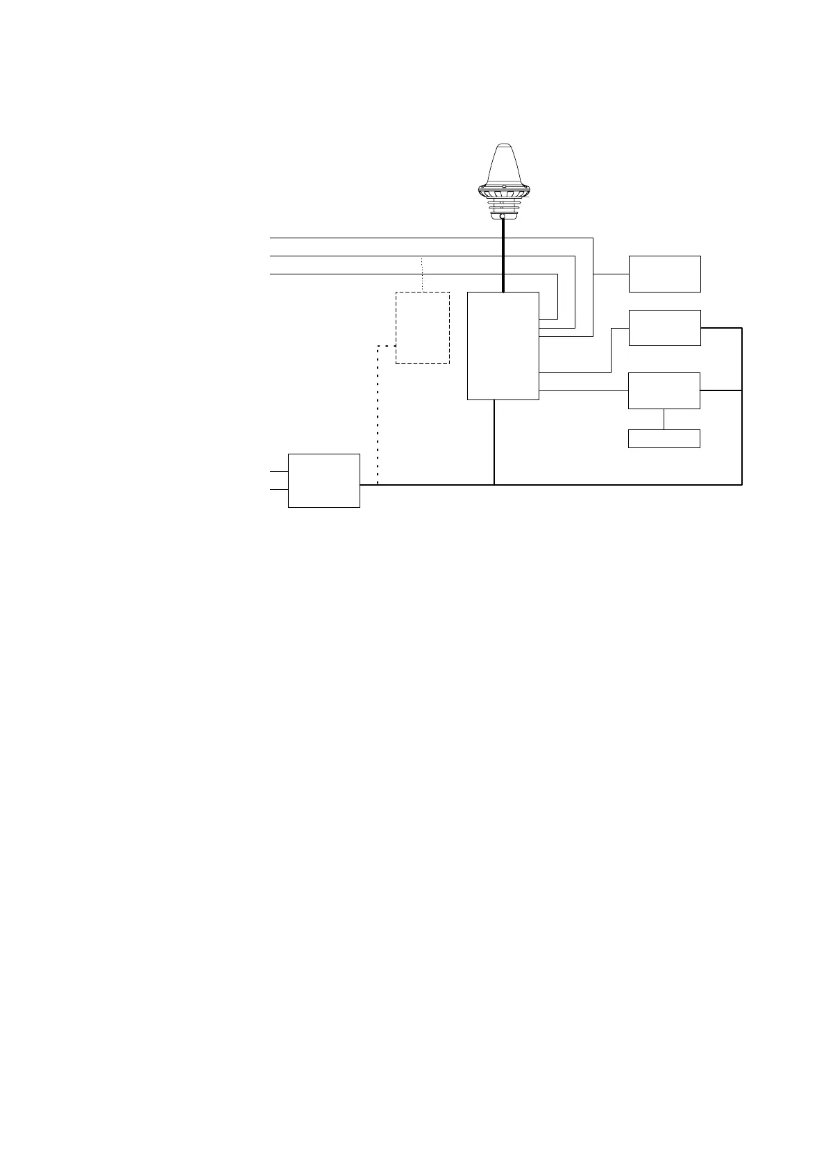
Figure 28 Interconnection diagram
The TT-3608A printer can be substituted with the compact
printer/alarm panel TT-3042D (please see section 3.9) if special
requirement exist for a compact solution.
For applications where cables will be handmade by the dealer or
the customer it is important to note that the cable screen should
be soldered to the connector frame to prevent static electric
shocks. A complete set of connectors are delivered together with
an Integrated Capsat System.
Document Nr: I-MA-3010.68-5510-762-IVT-312