System Installation
System InstallationSystem Installation
System Installation TT-3606E Message Terminal
TT-3606E Message TerminalTT-3606E Message Terminal
TT-3606E Message Terminal
Page
PagePage
Page 3-24
3-243-24
3-24 25-Jul-00
25-Jul-0025-Jul-00
25-Jul-00
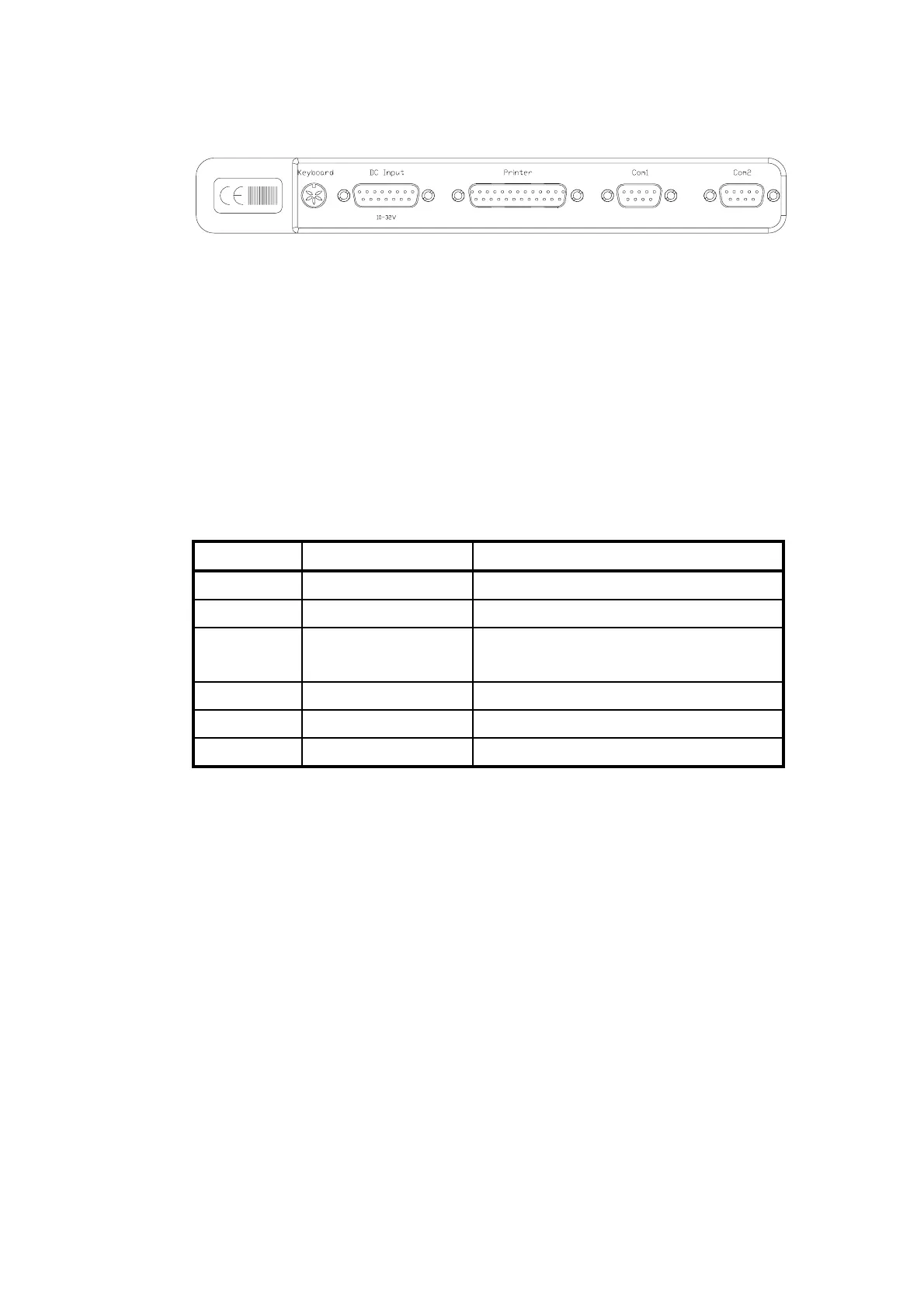
Figure 14 TT-3606E Rear Connectors
3.4.1.1 Power connector
The power input connector is a standard 15 pin SubD male con-
nector, located on the rear panel of the TT-3606E and the pin as-
signments are as indicated below. The Remote ON/OFF input
makes it possible to place an eventual on/off switch at any loca-
tion.
Pin Name Signal Description
1,2,9,10 + supply 10-32 VDC (Battery Positive input)
4,5,12,13 - supply DC Return (Battery Negative input)
6 Remote ON/OFF ON if connected to “- supply”
OFF if floating
7,8 SGND Chassis (Secondary GND)
Ground GND Shield
3,11,14,15 NC
Table 21 TT-3606E Power Connector
3.4.1.2 Communication port
The TT-3606E Message Terminal communicates with the TT-
3020C Capsat Transceiver via one of the two standard RS-423
ports, located on the rear panel.
The communication parameters are factory programmed to:
COM1, speed 4800 Baud, 8 databits, no
COM1, speed 4800 Baud, 8 databits, noCOM1, speed 4800 Baud, 8 databits, no
COM1, speed 4800 Baud, 8 databits, no
parity, 1 stopbit
parity, 1 stopbitparity, 1 stopbit
parity, 1 stopbit
Alternatively these settings may be customer defined.
Document Nr: I-MA-3010.68-5510-762-IVT-312