Antennas
AntennasAntennas
Antennas System Installation
System InstallationSystem Installation
System Installation
25-Jul-00
25-Jul-0025-Jul-00
25-Jul-00 Page
PagePage
Page 3-13
3-133-13
3-13
3.3.2.2 Antenna cable
The TT-3005A Antenna specifications requires that the total
maximal attenuation at 1.65 GHz must be less than 10 dB, and the
maximal total (short-circuited in one end) DC resistance must not
exceed 0.7 Ohms.
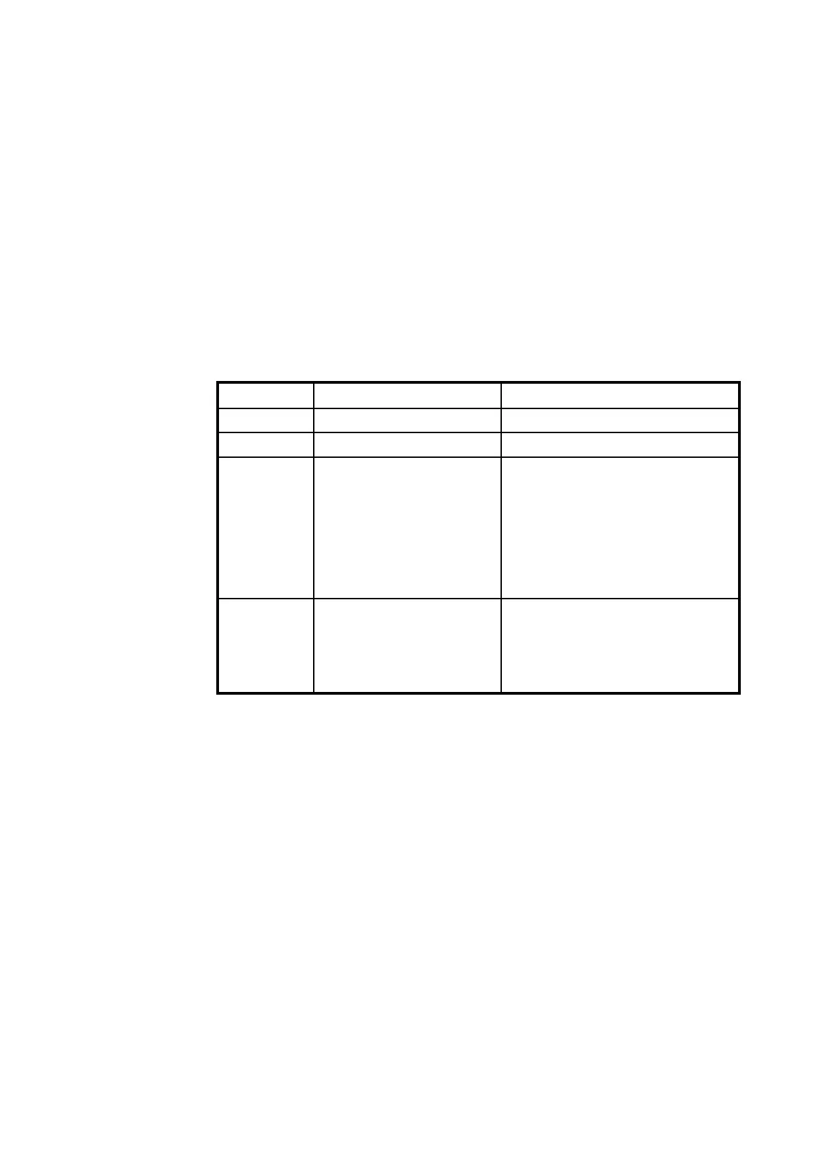
In case the antenna cable is to be produced on site, the cable
type should match the below listed guide-lines:
Range (m)
Range (m)Range (m)
Range (m) Cable type no.
Cable type no.Cable type no.
Cable type no. Connector type no. (Suhners)
Connector type no. (Suhners)Connector type no. (Suhners)
Connector type no. (Suhners)
1 - 10 RG-223U, 5.5 mm 11TNC-50-3-14c
11 - 25 RG-214U, 10.8 mm 11TNC-50-7-2c
26 - 50 Suhner:
SA7272, 10.0 mm
Nokia:
02Y(st)C2YC 2,7/7,3AF
The SA7272 cable with N
connectors (11N-50-7-35) and
two adapters N female to TNC
male (33TNC-N-50-51)
TNC male / TNC male
51 - 70 SA12272, 15.0 mm The SA12272 cable with N
connectors (11N-50-12-35C)
and two adapters N female to
TNC male (33TNC-N-50-51)
Table 17 TT-3020C Capsat Transceiver Antenna Cable types
(TNC - TNC) for TT-3005A antenna.
All antenna cables are double shielded.
The antenna cable may run together with radar or navigator ca-
bles. Separate cable ditch is not required.
If you install your system in a permanent location, we recommend
that you, after the installation of the antenna, wrap the connector
with the enclosed self-bonding tape, disabling water from pene-
trating the connection.
Document Nr: I-MA-3010.68-5510-762-IVT-312