Installation - TT-3020C
Installation - TT-3020CInstallation - TT-3020C
Installation - TT-3020C Connectors
ConnectorsConnectors
Connectors
Page
PagePage
Page 2-8
2-82-8
2-8 25-Jul-00
25-Jul-0025-Jul-00
25-Jul-00
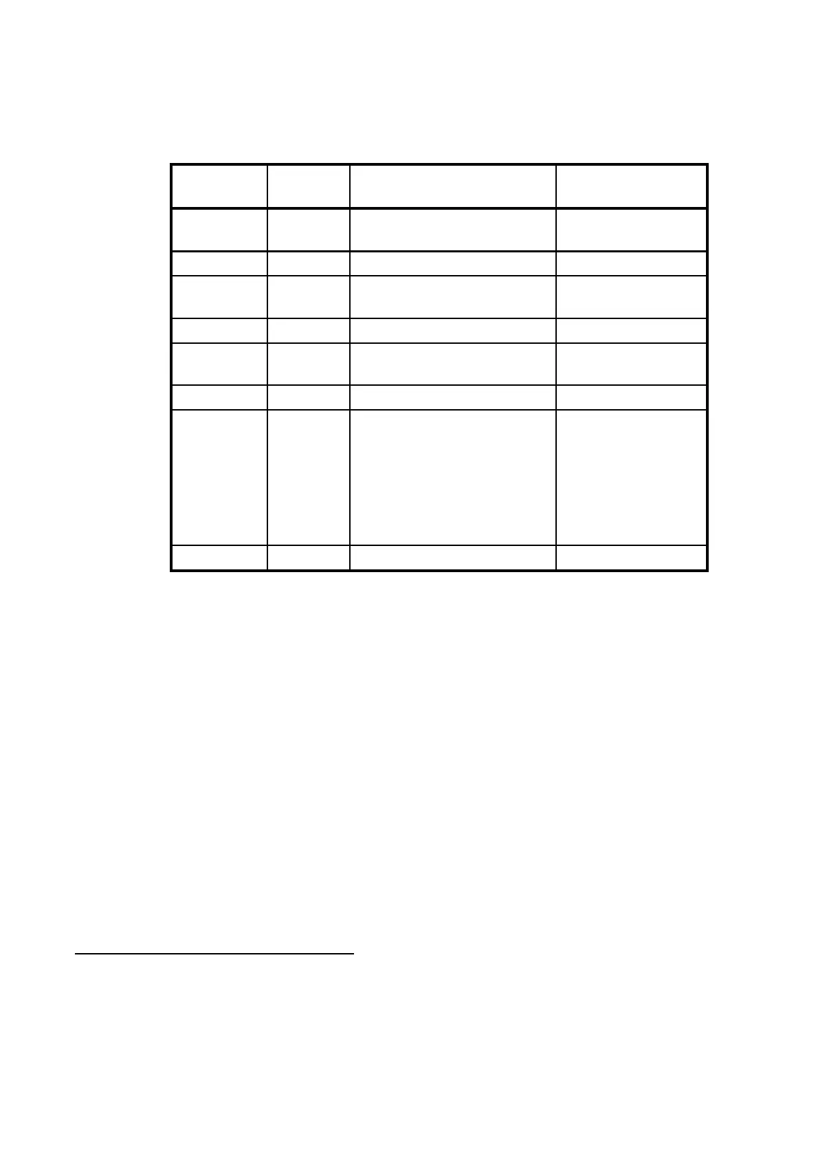
X1 Pins Name Signal Description DC Cable 37-
107881-A
1,2,9,10 SUP+ 10-32 VDC (Battery
Positive input)
Red 2.5mm
2
3NC
4,5,12,13 SUP- DC RN (Battery Negative
input)
Black 2.5mm
2
6 ON/OFF Remote ON/OFF
1
White 0.25mm
2
7,8 SGND Chassis (Secondary
GND)
11 NC
14,15 9V out Floating +9V out max
400mA on pin 14 & 15.
Ref. to Chassis (Secon-
dary GND)
Note: Max. load (400mA)
is a combination of this
output and X4 pin 5.
Secondary GND
Yellow/green
wire with
Transparent
connector
Ground GND Ground shield
Table 5 TT-3020C Capsat Transceiver DC Power Connector pin
assignment
Pin 6 is a unique feature for the TT-3020C Capsat Transceiver.
When this pin is left floating the Transceiver is turned off, but if
pin 6 is shorted to the negative terminal of the battery or DC-
supply, the Transceiver will be switched on. This makes it possi-
ble for external equipment to perform remote power control of
the TT-3020C.
The remote power control can be controlled by an external relay
or solid state switch.
1
This wire has to be connected to battery negative (black wire), to be
able to turn on. Please see section 2.4.1, On/Off features.
Document Nr: I-MA-3010.68-5510-762-IVT-312