Installation - TT-3020C
Installation - TT-3020CInstallation - TT-3020C
Installation - TT-3020C Connectors
ConnectorsConnectors
Connectors
Page
PagePage
Page 2-10
2-102-10
2-10 25-Jul-00
25-Jul-0025-Jul-00
25-Jul-00
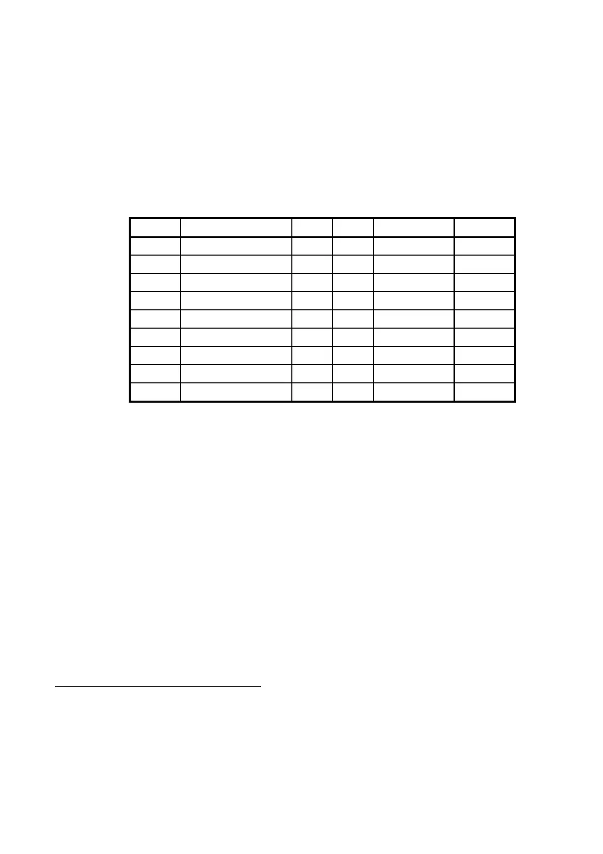
2.5.2.2 DTE Connector interface
The TT-3020C which is a DCE uses the signals listed in Table 7
(marked with a 9 in the
Used
column).Please notice that DTE pin
naming is used.
Name
NameName
Name Signal description
Signal descriptionSignal description
Signal description 9-Pin
9-Pin9-Pin
9-Pin Used
UsedUsed
Used Levels
LevelsLevels
Levels Direction
DirectionDirection
Direction
DCD Data Carrier Detect 1 EIA/TIA-232-E
Î
RxD Received Data 2
9
EIA/TIA-232-E
Î
TxD Transmitted Data 3
9
EIA/TIA-232-E
Í
DTR Data Terminal Ready 4
9
EIA/TIA-232-E
Í
GND Ground 5
9
DSR Data Set Ready 6
9
EIA/TIA-232-E
Î
RTS Request To Send 7
CTS Clear To Send 8
9
EIA/TIA-232-E
Î
RI
1
Ring Indicator 9
9
EIA/TIA-232-E
Î
Table 7 TT-3020C X3 pin assignment
The Î symbol means that the signal is generated by the Trans-
ceiver.
For full operating specifications for the serial interface, you are
kindly requested to refer to the CCITT Rec. V24 and the EIA/TIA-
232-E specifications.
2.5.2.3 Interfacing to peripherals
To Interface the TT-3020C to a TT-3606E Message Terminal, sim-
ply use the communication cable enclosed in the delivery.
1
The RI indicator goes high (approximately 8 Volts), when a message or
an EGC is received. RI is reset to low when the message/EGC has been
printed and/or routed to external printer/DTE equipment.
Document Nr: I-MA-3010.68-5510-762-IVT-312