TT-3042C Remote Alarm/Distress Box (optional)
TT-3042C Remote Alarm/Distress Box (optional)TT-3042C Remote Alarm/Distress Box (optional)
TT-3042C Remote Alarm/Distress Box (optional) System Installation
System InstallationSystem Installation
System Installation
25-Jul-00
25-Jul-0025-Jul-00
25-Jul-00 Page
PagePage
Page 3-43
3-433-43
3-43
The light intensity of the Power indicator can be adjusted by a
knob below it.
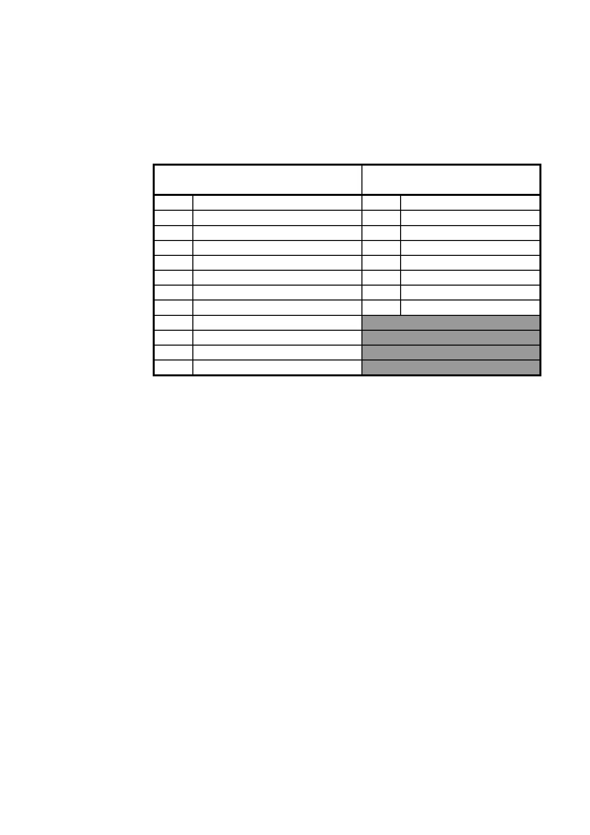
J1 PIN
J1 PINJ1 PIN
J1 PIN TT
TTTT
TT-3042C Description
-3042C Description-3042C Description
-3042C Description X4 PI
4 PI
X4 PI
4 PI
Satellite Communica-
tion Unit
1 + 7.5 - 12 Volt 5 +9Volt for ext. devices
2 GND + Safety GND † 6 GND
3 Distress button-lamp 1 In/Out 0
4 Buzzer/Buzzer knob 2 In/Out 1
5 To Distress Relay 3 In/Out 2
6 To Fault Relay 4 In/Out 3
7 Distress button 14 In 4
8GND 15In 5
9 Distress Relay contact pole 1
10 Distress Relay contact pole 2
11 Fault Relay contact pole 1
12 Fault Relay contact pole 2
Table 27 TT-3042C and Satellite Communication Unit inter-
connection
Note †: Cable screen included
The cable used for the connection between the TT-3042C Remote
Alarm/Distress Box and the TT-3020C Transceiver, has to be cho-
sen in accordance with the specifications in Table 28 TT-3042C
Technical Specifications.
The Remote Alarm/Distress Box is in full compliance with the In-
marsat CN114, IEC 945 and Wheel Mark specifications.
Document Nr: I-MA-3010.68-5510-762-IVT-312