System Installation
System InstallationSystem Installation
System Installation TT-3042D Remote Alarm / Printer Unit
TT-3042D Remote Alarm / Printer UnitTT-3042D Remote Alarm / Printer Unit
TT-3042D Remote Alarm / Printer Unit
Page
PagePage
Page 3-52
3-523-52
3-52 25-Jul-00
25-Jul-0025-Jul-00
25-Jul-00
3.9.2 Installation
To following brief outline may be used to get the TT-3042D up
and running as a printer together with a Thrane & Thrane trans-
ceiver which supports Arcnet - hardware as well as software wise.
1. Set an unique Arcnet address as described in section 3.9.1.
2. Connect the 3042D to the transceiver by means of the accom-
panying interconnection cable (15 pole SubD connectors).
3. Connect the 3042D to a DC power source by means of the ac-
companying power cable. For security reasons take care to
connect the ground/chassis wire properly to ground.
When power is applied it should now be possible for the trans-
ceiver to print on the TT-3042D when needed or initiated by the
user.
3.9.3 Connectors
The connectors for the TT-3042D are placed on the rear panel of
the printer unit.
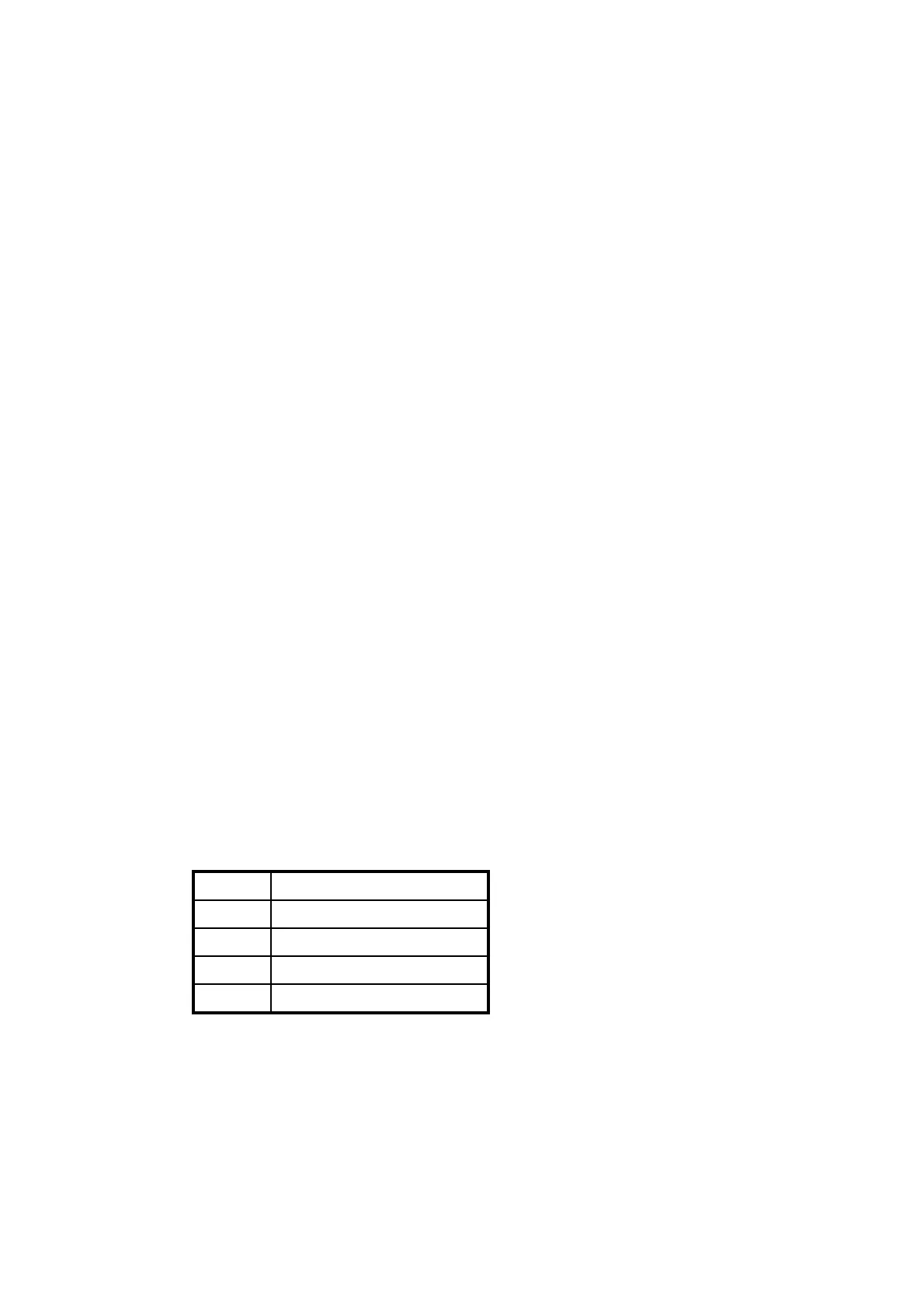
3.9.3.1 X1 Power In
The pinout of the power supply input is as listed in Table 30.
Pin Function
1 Battery Positive
2 Battery Negative
3Ground
4 Remote turn-on
Table 30 TT-3042D Power Connector
Document Nr: I-MA-3010.68-5510-762-IVT-312