-
30
-
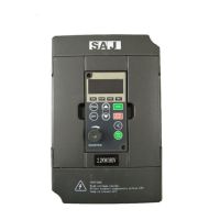
8000B Series
Type
Terminal
Symbol
Function
Interface
Standard
Computer
Communication
S+ 485 difference signal positive terminal
Standard RS485
communication
interface
S- 485 difference signal negative terminal
+5V Extension power positive terminal (+5V)
+15V Extension power positive terminal(+15V)
GND Extension power negative terminal
3.2.4 Descriptions of Control Circuit Terminals
Symbol Terminal Name Function
M1~M6
Multi-function
digital input
terminal
0.75-2.2kW (G): Digital terminals can not be connected
to power directly.
When connected to GND terminal, it is power-on and
the corresponding current is 10mA.
4kW and above: Optical coupling isolation input
compatible with +24V and COM.
Input voltage range:9-36V, input impedance:3.3kΩ
MO1
Multi-function
output terminal
(optical coupling isolating)Max. DC 48V/50mA
MCM
Common terminal
of multi-function
output terminal
(optical coupling isolating)Max. DC 48V/50mA
AVI
Analog input
terminal 1
Input voltage range:DC 0~10V (input impedance:20kΩ)
ACI
Analog input
terminal 2
1. input range:DC 0-10V or 0/4~20mA. It is selected
by jumper JP1 on control board. The default is current
input. 1-2Pin: voltage input; 2-3Pin: current input.
2. Input impedance:20kΩ when input voltage; 500Ω
when input current.
10V
Analog reference
voltage
10V ±5%,max. current: 30mA
GND
Analog grounding
terminal
Zero potential referring to +10V
FM
Analog output
terminal 1
FM:0~10V
 Loading...