SPA-100 OPERATION MANUAL
14 / 67
5. Equipment Setup
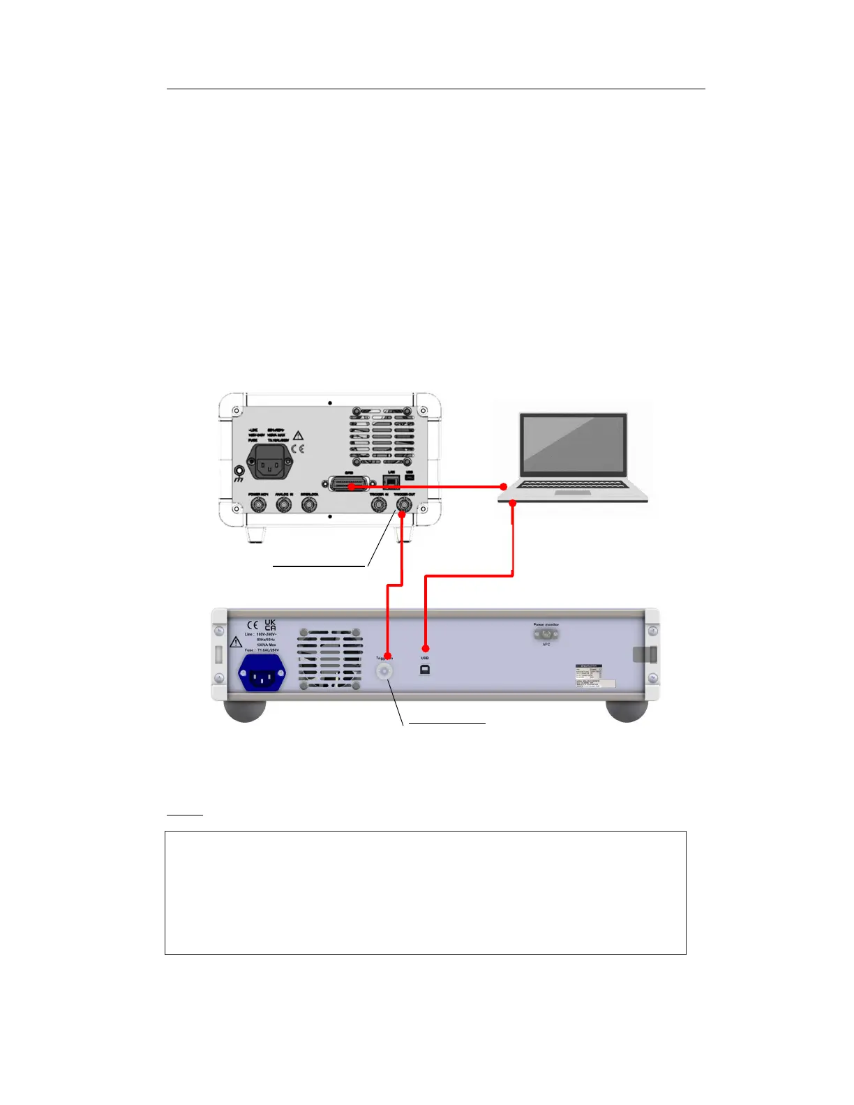
5.1 Rear cabling
1. Connect the trigger out pin of the TSL (TSL-570 in the figure) to the trigger
in terminal of the spa-100 with the attached BNC cable.
2. Connect the control computer to the SPA-100 using the supplied USB cable.
3. Connect the control computer and TSL with a GPIB cable (sold separately).
4. Connect the attached power cable to the power socket of the SPA-100.
NOTE
USB cable
(supplied)
GPIB
BNC Cable
(supplied)
TSL
(
Ex:TSL-570)
Control computer
SPA-100
The "POWER MONITOR" optical connector on the rear panel is an optical output
for monitoring the optical power that enters "PORT2" on the front panel during
transmission measurement. Approximately 80% of the optical power input to
PORT2 is output. Can be used for optical component alignment using transmitted
light power.
Figure 5-1 Rear cable connection diagram