EasyManuals Logo

Sanyo PLC-HP7000L Service Manual

Sanyo PLC-HP7000L
168 pages
To Next Page IconTo Next Page
To Previous Page IconTo Previous Page
Page #36 background imageLoading...
Page #36 background image
-36-
Optical Parts Disassembly
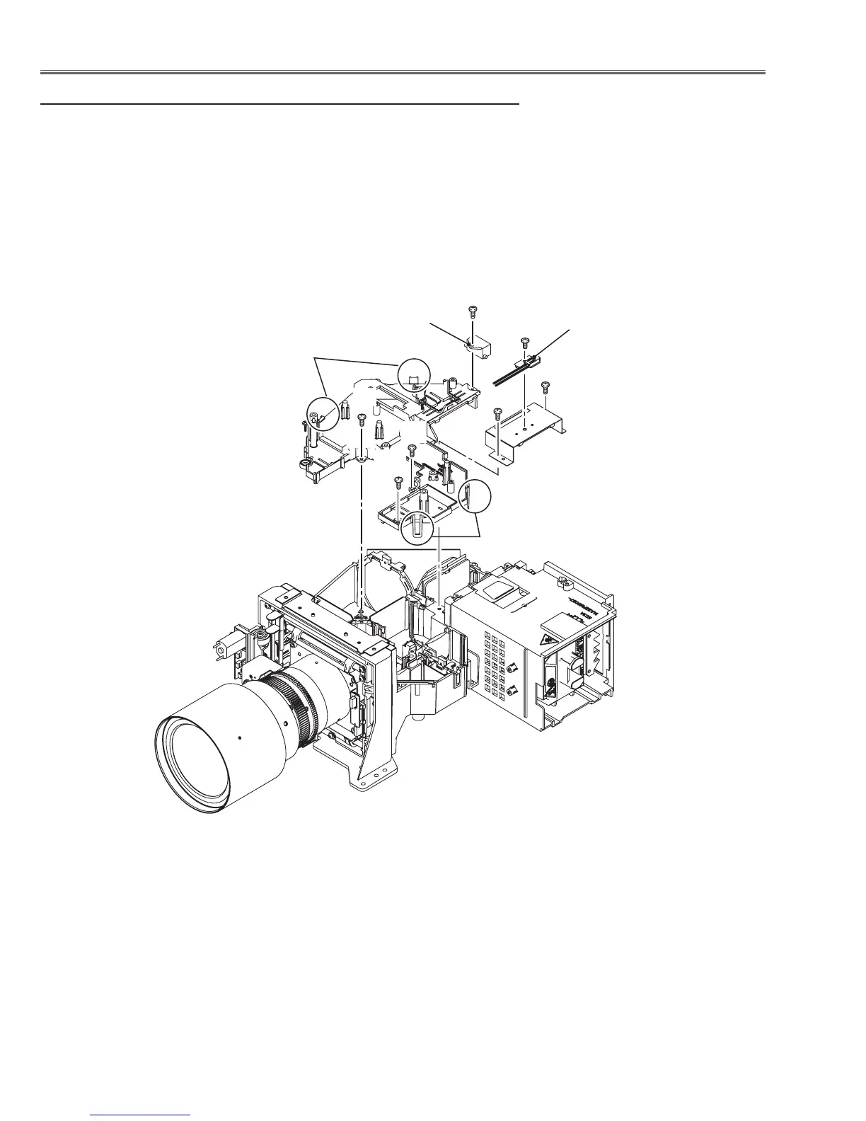
5 Optical base top removal
Before taking this procedure, remove cabinet top, main board following to the
chapter "Mechanical disassembly".
1 Remove 1 screw A (M3x6) on the thermal protector, 1 screw B (T3x10) on
the ballast trigger and 5 screws C (T3x10).
2 Unhook 4 hooks D on the optical base top and take the optical base top
upward off.
C
B
C
C
C
C
Thermal protector
Ballast trigger
D
D
A

Table of Contents

Other manuals for Sanyo PLC-HP7000L

Questions and Answers:

Question and Answer IconNeed help?

Do you have a question about the Sanyo PLC-HP7000L and is the answer not in the manual?

Sanyo PLC-HP7000L Specifications

General IconGeneral
BrandSanyo
ModelPLC-HP7000L
CategoryProjector
LanguageEnglish

Related product manuals