8 Operating Instructions YDP30 | YDP30-NET
Device Description
3 Device Description
3.1 Device Overview
9
8
7
26 5
34
110 1
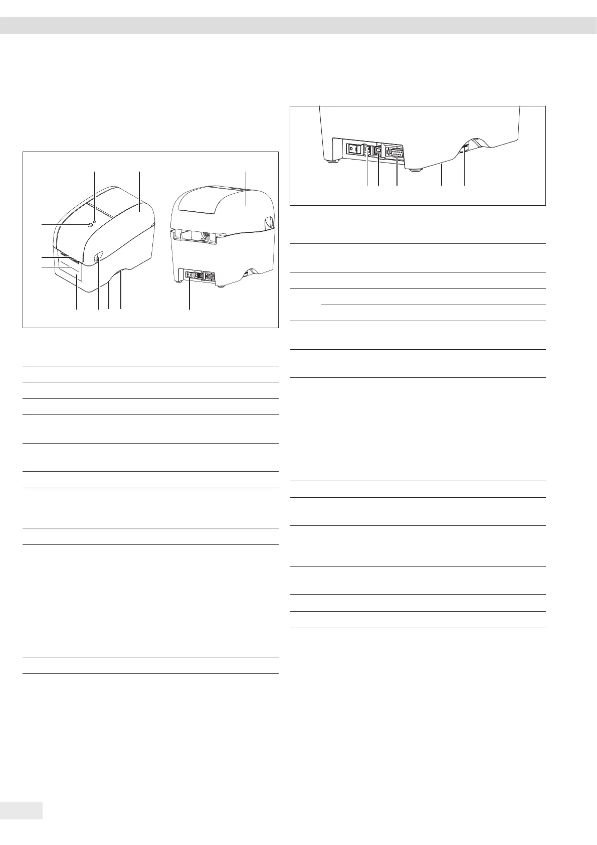
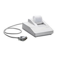
Fig. 1: YDP30 (front and rear view, example)
Pos. Name Description
1 Top cover
2 On/Off switch
3 Recessed grip
4 Manufacturer's ID
label
Attached to the underside of
the device.
5 Lever Is intended to open the top
cover.
6 Front cover
7 Release paper
opening
For the output of release paper
from self-adhesive media
(peel-off mode).
8 Paper output tray
9 Feed button − Is intended to move
inserted media forward, e.g.
when printing labels.
− Is intended to stop and
resume printing.
− Is intended to select certain
functions, e.g. configura-
tion of the RS232 interface,
calibration of sensors.
10 LED display
3.2 Connections
1 2 3 54
Fig. 2: Connections (rear view YDP30, example)
Pos. Name Description
1 Power connection Is intended to connect the
power supply cable.
2 USB USB port
3 RS-232C Serial interface, YDP30 only
Ethernet YDP30-NET only
4 Production
interface
No function
5 Interface for SD
memory card
No function
3.3 LED Display
The LED display denotes the device’s operating status.
Light color and
behavior
Description
Green The device is ready for use.
Flashing green The device is receiving data or a print
job has been stopped.
Illuminated yellow/
red
The device is connecting to the Wi-Fi
network or corporate network
(YDP30-NET only).
Illuminated yellow The device is deleting internally
stored data.
Illuminated red The top cover is open.
Flashing red There is a problem, e.g. a paper jam.