Operating Instructions YDP30 | YDP30-NET 9
Device Description
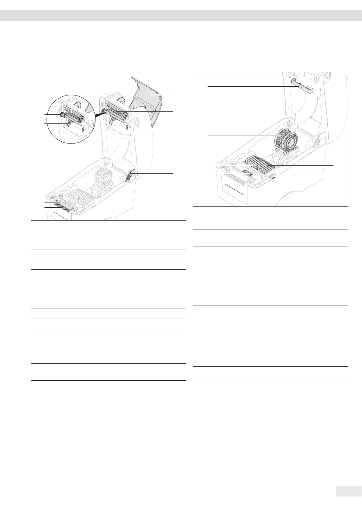
3.4 Components for Print Function and
Lock for Top Cover
1
2
3
5
4
6
7
8
Fig. 3: Components for print function and lock for top cover (top cover and ink
ribbon cover open, example)
Pos. Name Description
1 Ink ribbon cover
2 Print head
3 Lock for top cover Keeps the top cover in an
open position. This means
that the top cover
cannot close acciden-
tally.
4 Tear bar
5 Print roller
6 Intake for the ink ribbon
supply spool
7 Adjustment wheel to
wind the ink ribbon
8 Intake for the ink ribbon
take-up spool
3.5 Components for Media Feed
and Sensors
6
5
4
3
1
2
Fig. 4: Components for media feed (top cover open, example)
Pos. Name Description
1 Distance sensor
(transmitter)
2 Adjustment wheel for
media feed
Sets the media feed to the
width of the medium.
3 Sensor for black
marking
4 Media feed Keeps the inserted media in
position. Can be set to
different widths.
5 Media mount Holds the spool of the
medium. Consists of 2
mounts, the distance
between which can be
changed. The mounts can be
rotated 180°. This allows the
media mount to be set to 2
media spool sizes.
6 Distance sensor
(receiver)