15
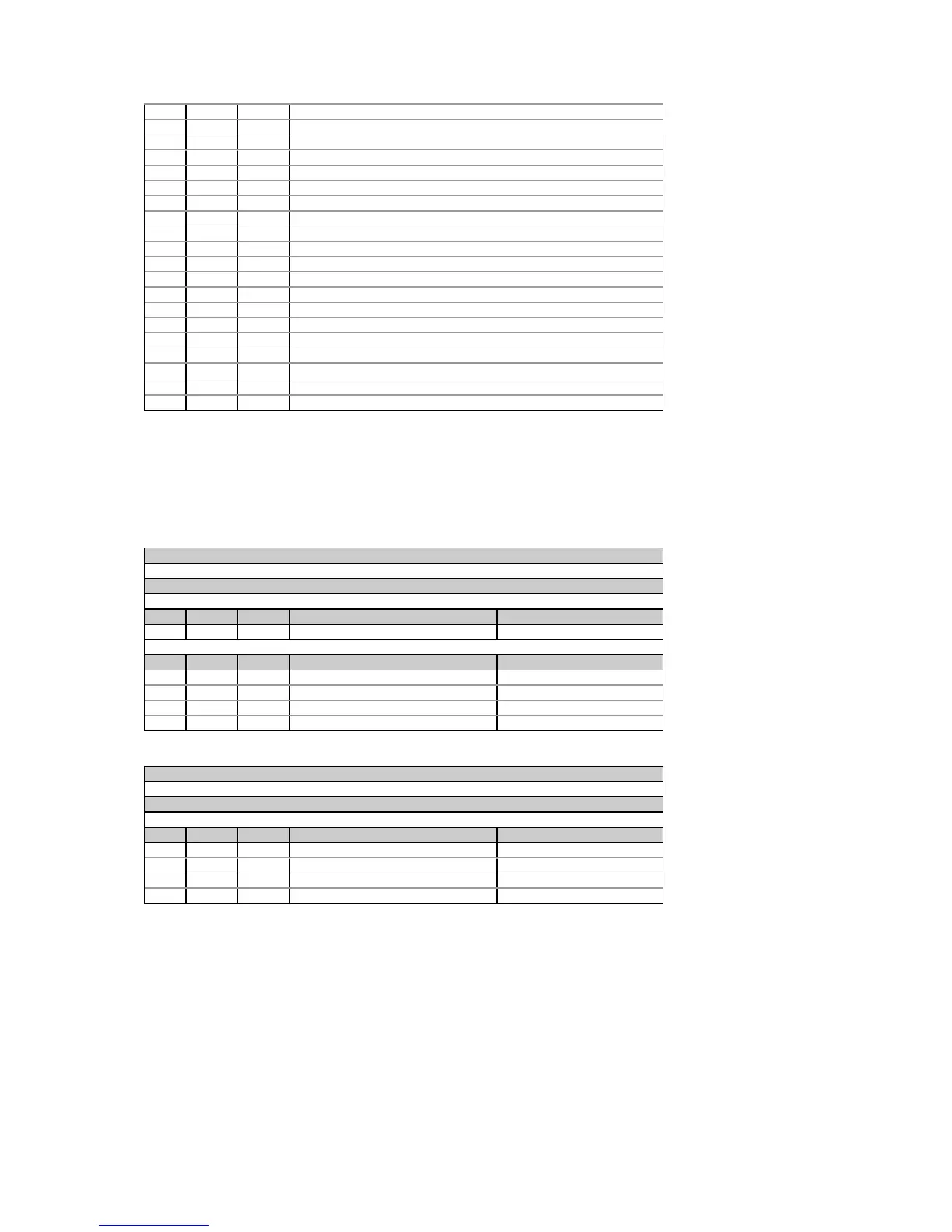
7 32 4 The number of logged records in data log #4
8 36 4 The number of logged records in data log #5
9 40 4 The number of logged records in data log #6
10 44 4 The number of logged records in data log #7
11 48 4 The number of logged records in data log #8
12 52 32 Not used
13 84 4 The number of logged records in waveform log #1
14 88 4 The number of logged records in waveform log #2
15 92 4 The number of new event log records
16 96 4 The number of new data log #1 records
17 100 4 The number of new data log #2 records
18 104 4 The number of new data log #3 records
19 108 4 The number of new data log #4 records
20 112 4 The number of new data log #5 records
21 116 4 The number of new data log #6 records
22 120 4 The number of new data log #7 records
23 124 4 The number of new data log #8 records
24 128 32 Not used
25 160 4 The number of new waveform log #1records
26 164 4 The number of new waveform log #2 records
The number of logged records includes all records currently logged in the memory partition. The number of the
new records includes the number of records that are logged after the last read request has been issued for the
memory partition.
4.8 Analog Output Allocation
Table 4-19 Read Request
Message type (ASCII)
‘B’
Message body (hexadecimal)
Request
Field Offset Length Parameter Range
1 0 2 Analog channel number 0-1 = channel #1-#2
Response
Field Offset Length Parameter Range
1 0 2 Analog channel number 0-1 = channel #1-#2
2 2 4 Output parameter point ID see Table 4-23
3 6 8 Zero scale (0/4 mA) see Table 4-23
4 14 8 Full scale (20/1 mA) see Table 4-23
Table 4-20 Write Request
Message type (ASCII)
‘b’
Message body (hexadecimal)
Request/Response
Field Offset Length Parameter Range
1 0 2 Analog channel number 0-1 = channel #1-#2
2 2 4 Output parameter point ID see Table 4-23
3 6 8 Zero scale (0/4 mA) see Table 4-23
4 14 8 Full scale (20/1 mA) see Table 4-23
1. Except for the signed power factor (see Note 3 to Table 4-23), the output scale is linear within the value range. The scale
range will be inverted if the full scale specified is less than the zero scale.
2. For bi-directional analog output (±1 mA), the zero scale corresponds to the center of the scale range (0 mA) and the
direction of the current matches the sign of the output parameter. For signed (bi-directional) values, such as powers and
signed power factor, the scale is always symmetrical with regard to 0 mA, and the full scale corresponds to +1 mA output
for positive readings and to -1 mA output for negative readings. For these, the zero scale (0 mA output) is permanently set
in the instrument to zero for all parameters except the signed power factor for which it is set to 1.000. In the write
request, the zero scale is ignored. No error will occur when you attempt to change it. Unsigned parameters are output
within the current range 0 to +1 mA and can be scaled using both zero and full scales as in the case of single-ended
analog output.

 Loading...


