36
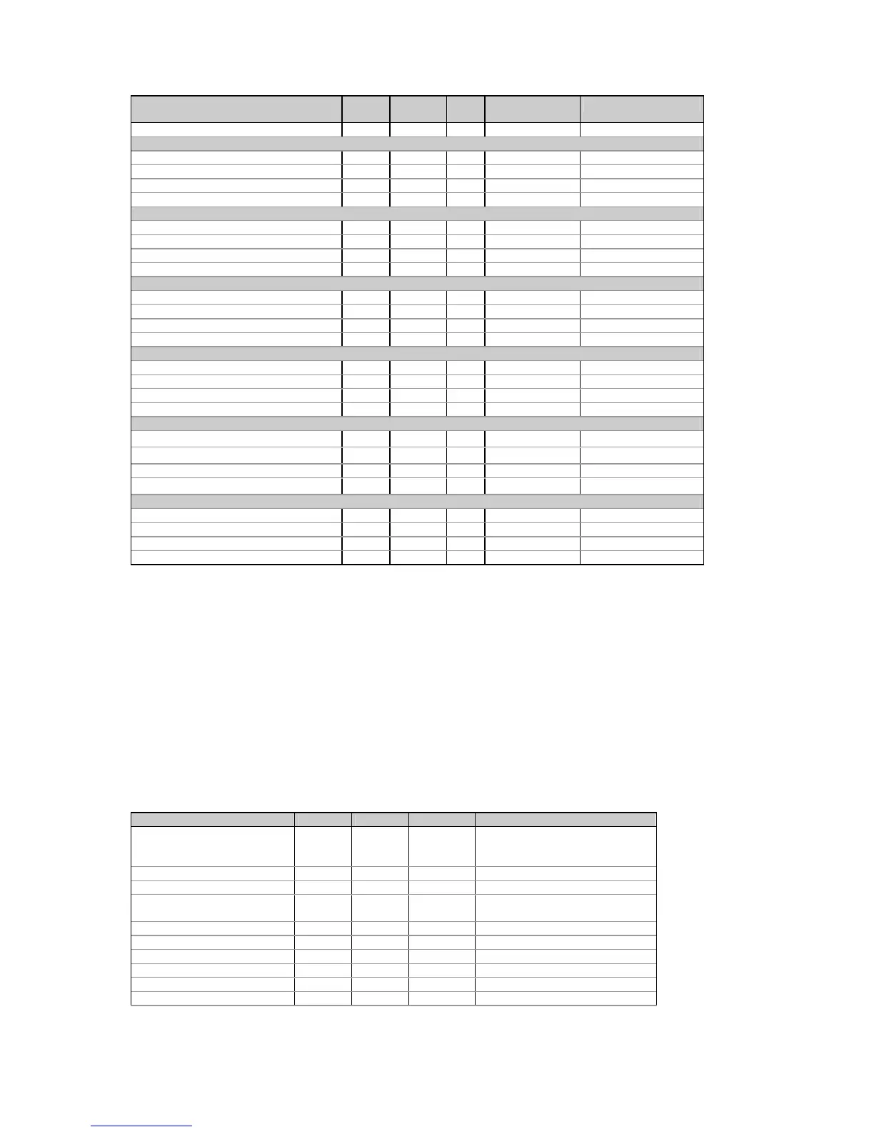
Parameter Point
ID
Type R/W Unit
Range
1
Harmonic H40 angle 0x6427 INT16 R 0.1 degree -1800 to 1800
L3 voltage harmonic angles
Harmonic H01 angle 0x6400 INT16 R 0.1 degree -1800 to 1800
Harmonic H02 angle 0x6401 INT16 R 0.1 degree -1800 to 1800
... ...
Harmonic H40 angle 0x6427 INT16 R 0.1 degree -1800 to 1800
L1 current harmonic angles
Harmonic H01 angle 0x6400 INT16 R 0.1 degree -1800 to 1800
Harmonic H02 angle 0x6401 INT16 R 0.1 degree -1800 to 1800
... ...
Harmonic H40 angle 0x6427 INT16 R 0.1 degree -1800 to 1800
L2 current harmonic angles
Harmonic H01 angle 0x6400 INT16 R 0.1 degree -1800 to 1800
Harmonic H02 angle 0x6401 INT16 R 0.1 degree -1800 to 1800
... ...
Harmonic H40 angle 0x6427 INT16 R 0.1 degree -1800 to 1800
L3 current harmonic angles
Harmonic H01 angle 0x6400 INT16 R 0.1 degree -1800 to 1800
Harmonic H02 angle 0x6401 INT16 R 0.1 degree -1800 to 1800
... ...
Harmonic H40 angle 0x6427 INT16 R 0.1 degree -1800 to 1800
Generic TOU season tariff energy registers - only as a reference for TOU profile logs
Season tariff #1 register 0x7000 UINT32
5
0 to 10
9
-1
Season tariff #2 register 0x7001 UINT32
5
0 to 10
9
-1
... ...
Season tariff #16 register 0x700F UINT32
5
0 to 10
9
-1
Generic TOU season tariff maximum demand registers - only as a reference for TOU profile logs
Season tariff #1 register 0x7100 UINT32
5
0 to Pmax
Season tariff #2 register 0x7101 UINT32
5
0 to Pmax
... ...
Season tariff #16 register 0x710F UINT32
5
0 to Pmax
1
For parameter limits, see Note
1
to Table 4-1
2
When using direct wiring (PT Ratio = 1), voltages are transmitted in 0.1 V units, currents in 0.01 A units, and powers in
0.001 kW/kvar/kVA units. For wiring via PTs (PT Ratio > 1), voltages are transmitted in 1V units, currents in 0.01 A units,
and powers in 1 kW/kvar/kVA units.
3
New absolute min/max value (lag or lead).
4
The actual frequency range is 45.00 - 65.00 Hz.
5
The TOU energy and TOU maximum demand register unit matches the measurement unit of the input parameter for which
the register is allocated.
6
When the 4LN3 or 3LN3 wiring mode is selected, the voltages will be line-to-neutral; for any other wiring mode, they will be
line-to-line voltages.
(M) These parameters are logged to the Min/Max log.
5.3 Basic Setup Registers
Table 5-8 Basic Setup Registers
Parameter Register Type R/W Range
Wiring mode
1
0x8600 UINT16 R/W 0 = 3OP2, 1 = 4LN3, 2 = 3DIR2,
3 = 4LL3, 4 = 3OP3, 5 = 3LN3,
6 = 3LL3
PT ratio 0x8601 UINT16 R/W
10 to 65000 × 0.1
CT primary current 0x8602 UINT16 R/W 1 to 5000 A
Power demand period 0x8603 UINT16 R/W 1,2,5,10,15,20,30,60 min,
255 = external synchronization
2
Volt/ampere demand period 0x8604 UINT16 R/W 1 to 1800 sec
Averaging buffer size 0x8605 UINT16 R/W 8, 16, 32
Reset enable/disable 0x8606 UINT16 R/W 0 = disable, 1 = enable
Reserved 0x8607 UINT16 R Read as 65535
The number of demand periods 0x8608 UINT16 R/W 1 to 15
Reserved 0x8609 UINT16 R Read as 65535

 Loading...


