44
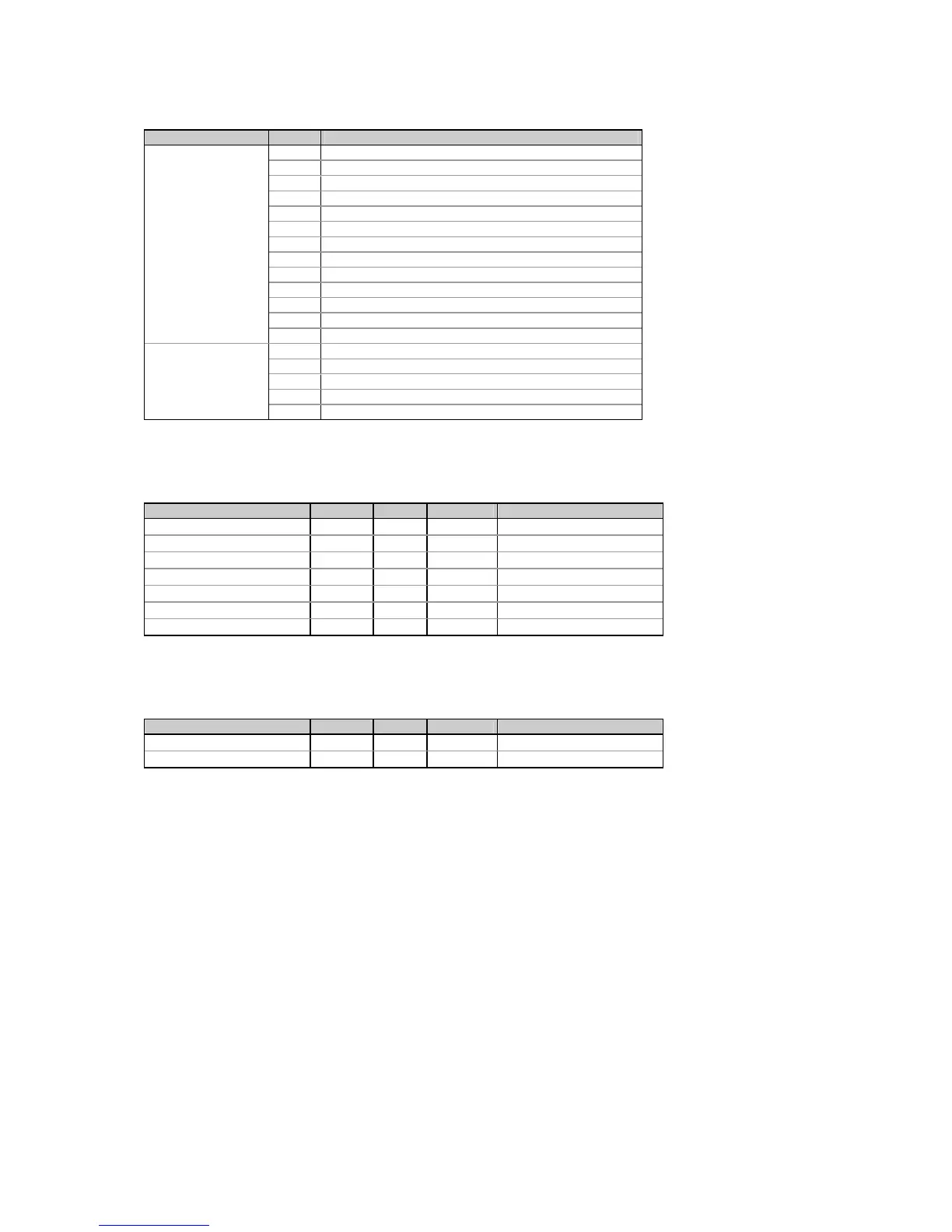
Table 5-18 Instrument Options
Options register Bit Description
Options1 0 120V option
1 690V option
2-5 Zeros
6 Analog output 0/4-20 mA
7 Analog output 0-1 mA
8
Analog output ±1 mA
9 Relays option
10 Digital inputs option
11 N/A
12 Setup is secured by a password (see Section 3.4)
13 ASCII compatibility mode is enabled (see Table 5-10)
14
Analog expander output ±1 mA
15 N/A
Options 2 0-2 Number of relays - 1
3-6 Number of digital inputs - 1
7-8 Number of analog outputs - 1
9-13 N/A
14-15 Memory module: 10 = 512 Kbytes
5.9 Extended Status Registers
Table 5-19 Extended Status Registers
Parameter Register Type R/W Range
Relay status 0x7D00
UINT16
R see Table 4-12
User event flags 0x7D01
UINT16
R see Table 4-13
Status inputs 0x7D02
UINT16
R see Table 4-14
Setpoint status 0x7D03
UINT16
R see Table 4-15
Log status 0x7D04
UINT16
R see Table 4-16
Active serial port number 0x7D05
UINT16
R 0 = Port 1, 1 = Port 2
Battery status 0x7D06
UINT16
R 0 = low, 1 = normal
5.10 Alarm Status Registers
Table 5-20 Alarm Status Registers
Parameter Register Type R/W Range
Setpoint alarm status 0x7E00
UINT16
R/W see Table 5-21
Self-check alarm status 0x7E01
UINT16
R/W see Table 5-22
The setpoint alarm register stores the status of the operated setpoints by setting the appropriate bits to 1. The
alarm status bits can be reset all together by writing zero to the setpoint alarm register. It is possible to reset each
alarm status bit separately by writing back the contents of the alarm register with a corresponding alarm bit set to
0.
The self-check alarm register indicates possible problems with the instrument hardware or setup configuration.
The hardware problems are indicated by the appropriate bits which are set whenever the instrument fails self-test
diagnostics or in the event of loss of power. The setup configuration problems are indicated by the dedicated bit
which is set when either configuration register is corrupted. In this event, the instrument will use the default
configuration. The configuration corrupt bit may also be set as a result of the legal changes in the setup
configuration since the instrument might implicitly change or clear other setups if they are affected by the changes
made.
Hardware fault bits can be reset by writing zero to the self-check alarm register. The configuration corrupt status
bit and RTC synchronization bit are also reset automatically when you change setup or update RTC either via the
front panel or through communications.

 Loading...


