53
5.16 Waveform Capture/Log Registers
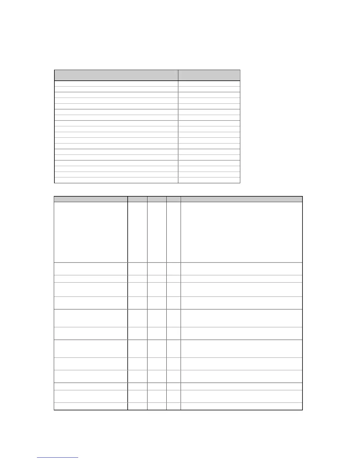
Table 5-35 Waveform Header Windows
Waveform header window Registers
(see Tables 5-36 - 5-37)
Real-time waveform capture channel V L1/L12 0xCE00-0xCE0D
Real-time waveform capture channel V L2/L23 0xCE0E-0xCE1B
Real-time waveform capture channel V L3 0xCE1C-0xCE29
Real-time waveform capture channel I L1 0xCE2A-0xCE37
Real-time waveform capture channel I L2 0xCE38-0xCE45
Real-time waveform capture channel I L3 0xCE46-0xCE53
Waveform log #1 channel V L1/L12 0xCE54-0xCE61
Waveform log #1 channel V L2/L23 0xCE62-0xCE6F
Waveform log #1 channel V L3 0xCE70-0xCE7D
Waveform log #1 channel I L1 0xCE7E-0xCE8B
Waveform log #1 channel I L2 0xCE8C-0xCE99
Waveform log #1 channel I L3 0xCE9A-0xCEA7
Waveform log #2 channel V L1/L12 0xCEA8-0xCEB5
Waveform log #2 channel V L2/L23 0xCEB6-0xCEC3
Waveform log #2 channel V L3 0xCEC4-0xCED1
Waveform log #2 channel I L1 0xCED2-0xCEDF
Waveform log #2 channel I L2 0xCEE0-0xCEED
Waveform log #2 channel I L3 0xCEEE-0xCEFB
Table 5-36 Waveform Header Window Registers
Parameter Offset Type R/W Range
Command/Status indication +0 UINT16 R Bit-mapped register:
bit 0 = 1 - the end record is being read (the end of a log file
reached)
bit 1 = 1 - reading after the end of file: the read pointer has
rolled over the end of a log file, i.e., the file is being re-read
from the beginning. This bit is cleared when a new record
is being read, or the read sequence has changed by
overwriting the partition pointer.
bit 8 = 1 - no records logged in the partition
bit 9 = 1 - the record is corrupted
bit 15 = 1 - read error (detailed by bits 8-9)
The record sequence number in the
log file
+1 UINT16 R 0 to 65535 (increments modulo 65536 with each log record)
The record timestamp
1
+2 UINT32 R Local time (UNIX-style)
Fractional seconds portion of
timestamp (milliseconds)
+3 UINT16 R 0-990 (at 10 ms resolution)
Trigger event setpoint ID +4 UINT16 R 1 to 16 = setpoint #1-#16,
0 = real-time waveform
The waveform series (compound
waveform) number
+5 UINT16 R 1 to 65535 (rolls over to 1 after 65535). Each series can
comprise up to 80 contiguous records of a compound
waveform
The record sequence number in the
waveform series
+6 UINT16 R 0 to 79
Analog input full scale, engineering
units (volts/amperes)
(ANALOG_SCALE)
+7 UINT32 R For the analog input scale units and range, refer to those of
voltage and current in Table 5-7
Digital full scale for the channel,
sample code (DIGITAL_SCALE)
+8 UINT16 R 1023 (10 bit A/D), 4095 (12 bit A/D), 8191 (13 bit A/D).
Corresponds to twice the analog input full scale range.
Zero offset, code (ZERO_OFFSET) +9 UINT16 R Corresponds to the center of the digital sample's full scale
range
Sampling frequency +10 UINT16 R 0 to 6500 x 0.01Hz
Trigger sample point offset in the
waveform series
+11 UINT16 R 0-511 (corresponds to the first record in the series)
Reserved +12, 13 UINT16 R 0

 Loading...


