57
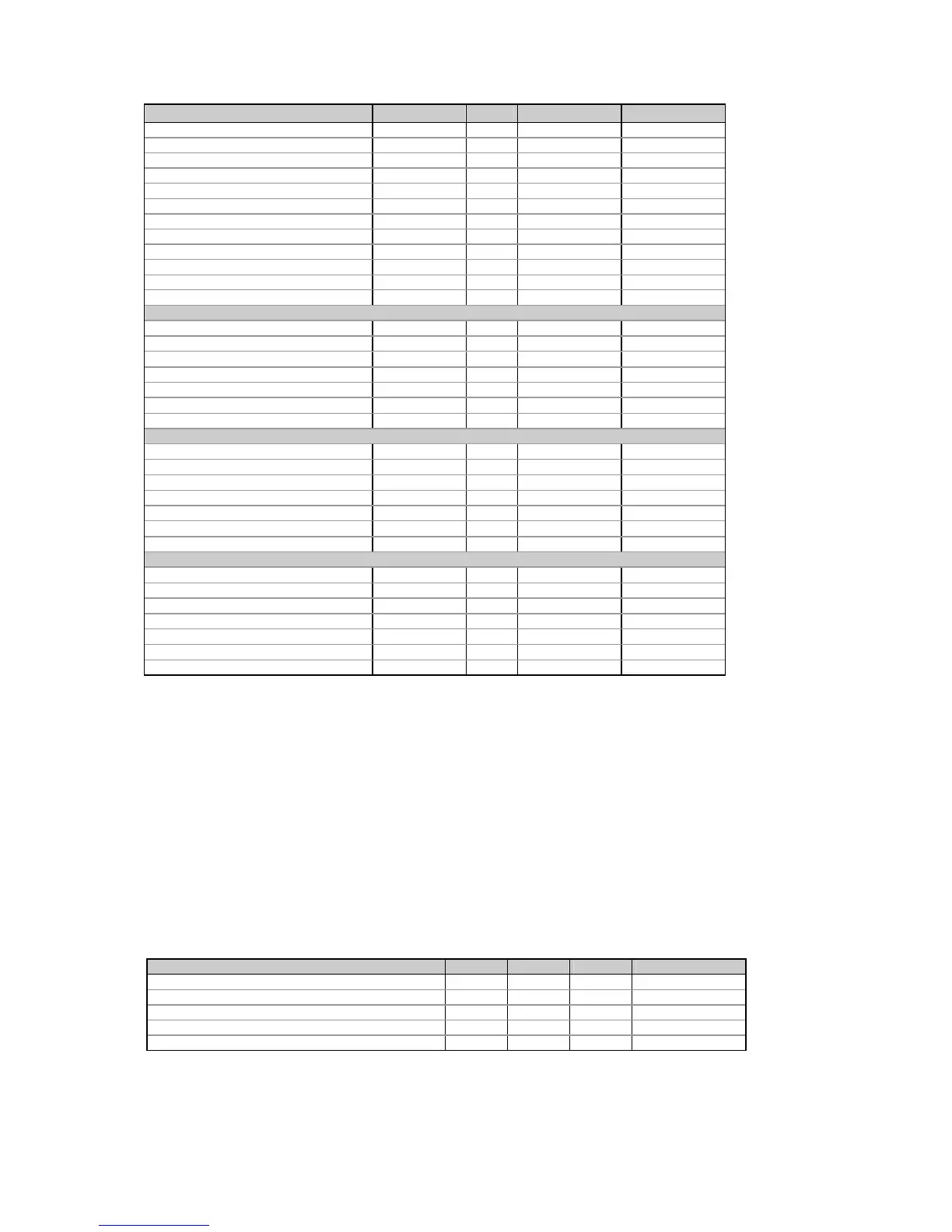
Parameter Register Type
Unit
2
Range
1
Timestamp 0xB389 UINT32
Max. ampere demand L3 0xB38A UINT32 0.01A 0 to Imax
Timestamp 0xB38B UINT32
Reserved 0xB38C-0xB391 0
Max. sliding window kW import demand 0xB392 UINT32 0.001kW/1kW 0 to Pmax
Timestamp 0xB393 UINT32
Reserved 0xB394-0xB395 UINT32
Max. sliding window kVA demand 0xB396 UINT32 0.001kVA/1kVA 0 to Pmax
Timestamp 0xB397 UINT32
Reserved 0xB398-0xB39D 0
Max. sliding window kW export demand 0xB39E UINT32 0.001kW/1kW 0 to Pmax
Timestamp 0xB39F UINT32
TOU maximum demand register #1
Max. Demand Tariff #1 register 0xB480 UINT32 5
0 to Pmax
Timestamp 0xB481 UINT32
Max. Demand Tariff #2 register 0xB482 UINT32 5
0 to Pmax
Timestamp 0xB483 UINT32
...
Max. Demand Tariff #16 register 0xB49E UINT32 5
0 to Pmax
Timestamp 0xB49F UINT32
TOU maximum demand register #2
Max. Demand Tariff #1 register 0xB500 UINT32 5
0 to Pmax
Timestamp 0xB501 UINT32
Max. Demand Tariff #2 register 0xB502 UINT32 5
0 to Pmax
Timestamp 0xB503 UINT32
...
Max. Demand Tariff #16 register 0xB51E UINT32 5
0 to Pmax
Timestamp 0xB51F UINT32
TOU maximum demand register #3
Max. Demand Tariff #1 register 0xB580 UINT32 5
0 to Pmax
Timestamp 0xB581 UINT32
Max. Demand Tariff #2 register 0xB582 UINT32 5
0 to Pmax
Timestamp 0xB583 UINT32
...
Max. Demand Tariff #16 register 0xB59E UINT32 5
0 to Pmax
Timestamp 0xB59F UINT32
Timestamp is given in local time in a UNIX-style time format: it represents the number of seconds since midnight (00:00:00),
January 1, 1970. The time is valid after January 1, 2000.
1
For parameter limits, see Note
1
to Table 4-1
2
When using direct wiring (PT Ratio = 1), voltages are transmitted in 0.1 V units, currents in 0.01 A units, and powers in
0.001 kW/kvar/kVA units. For wiring via PTs (PT Ratio > 1), voltages are transmitted in 1V units, currents in 0.01 A units, and
powers in 1 kW/kvar/kVA units.
3
New absolute min/max value (lag or lead).
4
The actual frequency range is 45.00 - 65.00 Hz.
5
The TOU maximum demand register unit matches the measurement unit of the input parameter for which the register is
allocated.
6
When the 4LN3 or 3LN3 wiring mode is selected, the voltages will be line-to-neutral; for any other wiring mode, they will be
line-to-line voltages.
5.18 Digital Inputs Allocation Registers
Table 5-39 Digital Inputs Allocation Registers
Parameter Register Type R/W Range
Status inputs allocation mask 0x8900 UINT16 R
1
See Table 5-37
Pulse inputs allocation mask 0x8901 UINT16 R/W See Table 5-37
Not used 0x8902 UINT16 R
1
Read as 0
External demand synchronization input mask 0x8903 UINT16 R/W See Table 5-37
Time synchronization input mask 0x8904 UINT16 R/W See Table 5-37
1
Writing to these locations is ignored. No error will occur.

 Loading...


