17
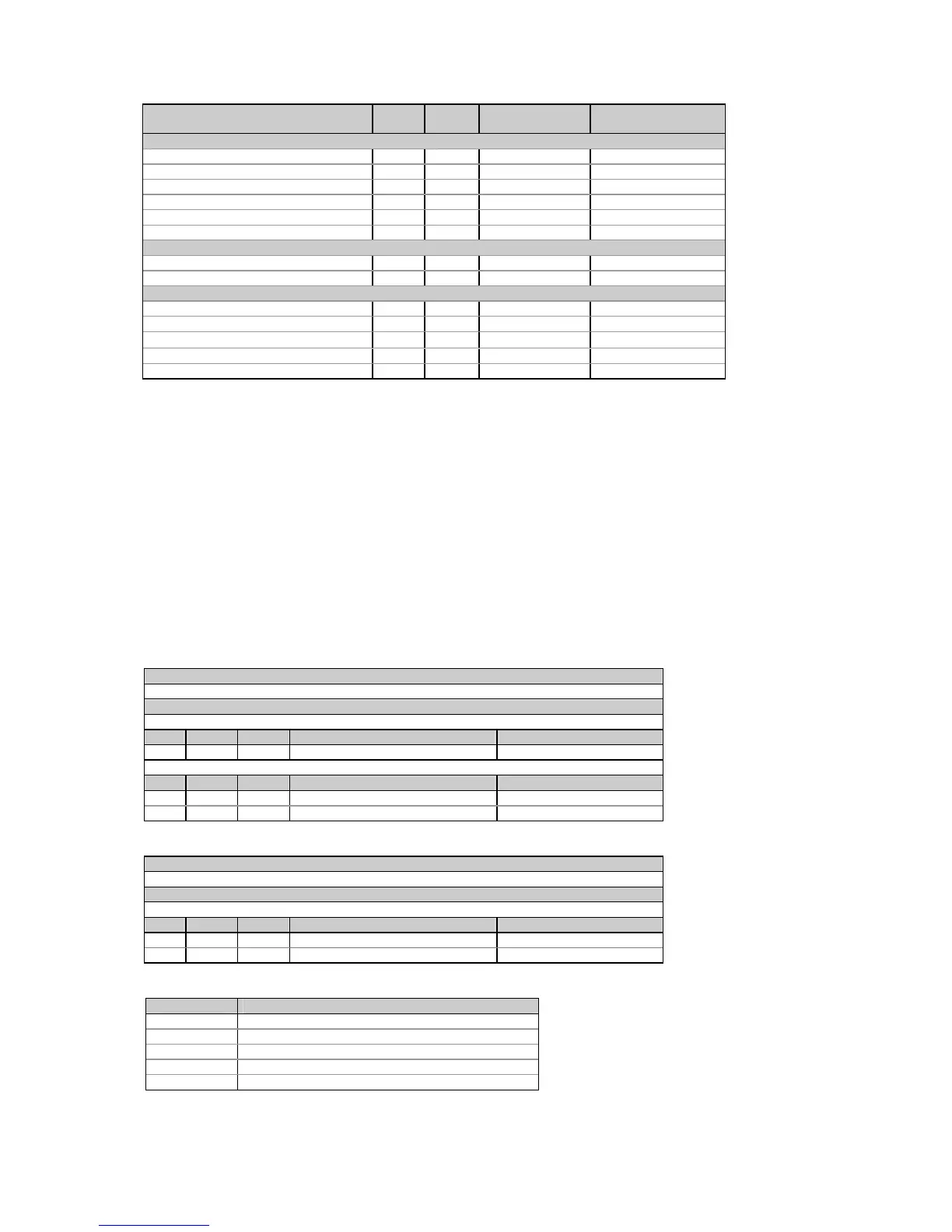
Parameter Point
ID
Length Unit
2
Scale range
1
Average total values
Total kW 0x1400 8 0.001kW/1kW -Pmax to Pmax
Total kvar 0x1401 8 0.001kvar/1kvar -Pmax to Pmax
Total kVA 0x1402 8 0.001kVA/1kVA 0 to Pmax
Total PF
4
0x1403 4 0.001 -999 to 1000
Total PF Lag 0x1404 4 0.001 -999 to 1000
Total PF Lead 0x1405 4 0.001 -999 to 1000
Average auxiliary values
Neutral current 0x1501 8 0.01A 0 to Imax
Frequency 0x1502 4 0.01Hz 0 to 10000
3
Present demands
Accumulated kW import demand 0x160F 8 0.001kW/1kW 0 to Pmax
Accumulated kvar import demand 0x1610 8 0.001kvar/1kvar 0 to Pmax
Accumulated kVA demand 0x1611 8 0.001kVA/1kVA 0 to Pmax
Accumulated kW export demand 0x161A 8 0.001kW/1kW 0 to Pmax
Accumulated kvar export demand 0x161B 8 0.001kvar/1kvar 0 to Pmax
1
For parameter limits, see Note
1
to Table 4-1.
2
When using direct wiring (PT Ratio = 1), voltages are transmitted in 0.1 V units, currents in 0.01 A units, and powers in
0.001 kW/kvar/kVA units. For wiring via PTs (PT Ratio > 1), voltages are transmitted in 1V units, currents in 0.01 A units,
and powers in 1 kW/kvar/kVA units.
3
The actual frequency range is 45.00 to 65.00 Hz
4
The output scale for signed (bi-directional) power factor is symmetrical with regard to ±1.000 and is linear from -0 to
-1.000, and from 1.000 to +0 (note that -1.000 ≡ +1.000). Negative power factor is output as [-1.000 minus measured
value], and non-negative power factor is output as [+1.000 minus measured value]. To define the entire range for power
factor from -0 to +0, the scales would be specified as -0/0. Because of the fact that negative zero may not be transmitted,
the value of -0.001 is used to specify the scale of -0, and both +0.001 and 0.000 are used to specify the scale of +0. To
define the range of -0 to 0, you must send -1/1 or -1/0 (considering the modulus of ×0.001).
5
When the 4LN3 or 3LN3 wiring mode is selected, the voltages will be line-to-neutral; for any other wiring mode, they will be
line-to-line voltages.
4.10 Digital Inputs Allocation
Table 4-24 Read Request
Message type (ASCII)
‘D’
Message body (hexadecimal)
Request
Field Offset Length Parameter Range
1 0 2 Digital input group ID see Table 4-26
Response
Field Offset Length Parameter Range
1 0 2 Digital input group ID see Table 4-26
2 2 2 Allocation mask see Table 4-27
Table 4-25 Write Request
Message type (ASCII)
‘d’
Message body (hexadecimal)
Request/Response
Field Offset Length Parameter Range
1 0 2 Digital input group ID see Table 4-26
2 2 2 Allocation mask see Table 4-27
Table 4-26 Digital Input Groups
Group ID Description
0 Status inputs
1
1 Pulse inputs
2 Not used (read as 0)
1
3 External demand synchronization pulse input
4 Time synchronization pulse input

 Loading...


